4.3 REAR PANEL
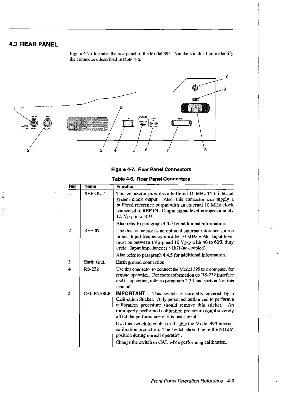
Figure 4-7 illustrates the rear panel
of
the Madel 395. Numbers in this figure identify
the connectors described in table 4-6.
10
9
2
3 4
5
6
7
8
Ref
1
2
3
4
5
Name
REFOUT
REFIN
EarthGnd.
RS-232
CAL
ENABLE
Figure 4-7. Rear Panel Connectors
Table 4-6. Rear Panel Connectors
Function
This connector provides a buffered 10
MHz
'!TL
internaI
system
dock
output. Also, this connector can supply a
buffered reference output with an external 10
MHz
clock
connected to REF IN. Output signallevel is approximately
1.5 Vp-p into
50n.
Aiso refer to paragraph 4.4.5 for additional information.
Use this connector as an optional external reference source
input. Input frequency
must
be 10
MHz
±5%. Input level
must
be
between 1Vp-p and 10 Vp-p with
40
ta
60%
dut
y
cycle. Input impedance is
>lill
(ac coupled).
Also refer to paragraph 4.4.5 for additional information.
Earth ground connection.
Use this connector to connect the Model 395
ta
a computerfor
remote operation. For more information on RS-232 interface
and its operation, refer
ta
paragraph 2.7.1 and section 5
of
this
manual.
IMPORTANT - This switch is normally covered by a
Calibration Sticker. Only personnel authorlzed to perform a
calibration procedure should remove this sticker. An
improperly performed calibration procedure could severely
affect the performance
of
this instrument.
Use this switch to enable
or
disable the Model 395 internaI
calibration procedure. The switch should
be
in the
NüRM
position durlng normal operation.
Change the switch to CAL when performing calibration.
Front Panel Operation Reference 4-9
Artisan Technology Group - Quality Instrumentation ... Guaranteed | (888) 88-SOURCE | www.artisantg.com