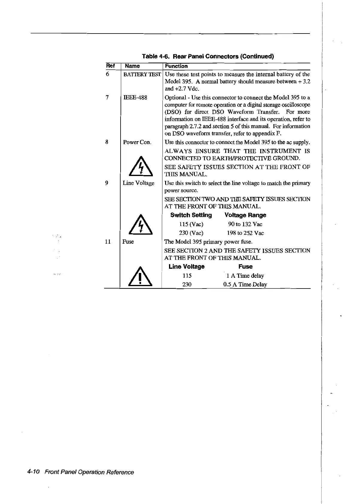
Table 4-6. Rear
Panel
Connectors (Continued)
Ref
Name Function
6
BATTERY
TEST
Use
these
test points to
measure
the internaI battery
of
the
Mode1395. A normal battery should measure between + 3.2
and +2.7 Vdc.
7
8
9
11
IEEE-488
Power Con.
Line Voltage
Fuse
Optional - Use this connectorto connect the Model 395 to a
computer for remote operation or a digital storage oscilloscope
(DSO) for direct
DSO
Waveform Transfer.
For
more
information on IEEE-488 interface and its operation, refer to
paragraph 2.7.2 and section 5
ofthis
manual. For information
on
DSO
waveform transfer, refer to appendix
F.
Use this connector to connectthe Model 395 to the ac supply.
ALWAYS
ENSURE
THAT
THE
INSTRUMENT
IS
CONNECTED
TO
EARTHIPROTECTIVE GROUND.
SEE
SAFETY
ISSUES
SECTION
AT
THE
FRONT
OF
THIS MANUAL.
Use this switch to select the line voltage to match the primary
power
source.
SEE SECTIONTWO
AND
THE
SAFETY ISSUES SECTION
AT
THE
FRONT
OF
THIS MANUAL.
Switch Setting Voltage Range
115 (Vac)
90
to 132
Vac
230
(Vac) 198 to
252
Vac
The
Model
395 primary
power
fuse.
SEE
SECTION
2
AND
THE
SAFETY
ISSUES
SECTION
AT
THE
FRONT
OF
THIS
MANUAL.
Une
Voltage Fuse
115 1 A Time delay
230
0.5 A
Time
Delay
4-10 Front Panel Operation Reference
Artisan Technology Group - Quality Instrumentation ... Guaranteed | (888) 88-SOURCE | www.artisantg.com