DSR Internally connected
10
pins 1 (DCD) and 4 (D1R) in the mode1395. Alogie
'0'
signifies that the 395 is ready for communication. See notes for DTR.
RTS Alogie
'0'
on this pin indieates that the device thatis connectedto the 395 is ready
to receive data. When handshaking is disabled, tbis tine is ignored by the 395.
The length
of
time that the 395 will wait before aborting transmission can he set
in the RS-232 setup screen (see section 5). The Mode1395 will respond
ta alogie
'1'
with a transmission latency
of
one character.
CTS A
logic
'0'
indicates
that
the
Model
395
is
ready
to
receive
data.
When
handshaking is enabled, this tine is driven
10
logic '1' when the 395 receive buffer
is about
213
full. Data will continue to be
s10red
in the buffer until itis full. This
line
will he driven to a logic
'0'
when the buffer drops helow
213
full. To prevent
data loss, this tine should be connected and recognized by the other device.
NOTES:
Although communication can he accomplished using only the Transmit
and Receive tines, it is recommended that the groundand handshake
Hnes are connected so
no
data is lost
due
to the bigh transfer rates
possible with the Mode1395.
Software handshaking ( XON
1XOFF ) is not supported by the Model
395.
The
Model395
data format
is
8 data bits, no parity, 1 stop bit.
2.11.2 IEEE-488 (Option 001)
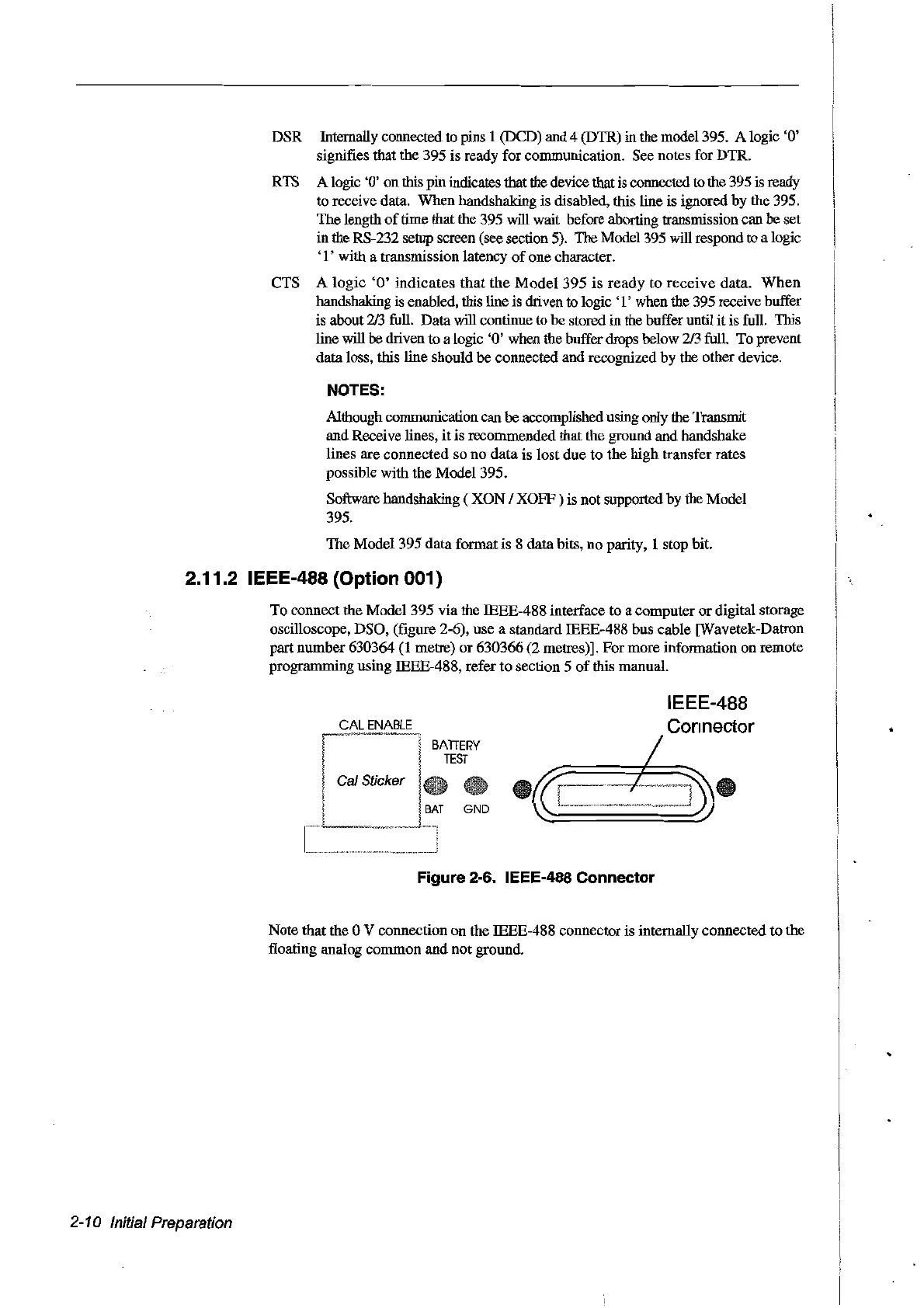
To
connect the Model 395 via the IEEE-488 interface to a computer or digital storage
oscilloscope, DSO, (figure 2-6), use a standard IEEE-488 bus cable [Wavetek-Datron
part number 630364
(1
metre) or 630366 (2 metres)]. For more information on remote
programming using IEEE-488, refer
to
section 5
of
tbis manual.
CALENABLE
BATTERY
TEST
Ca! Sticker
BAT
GND
Figure 2-6. IEEE-488 Connector
Note that the 0 V connection on the IEEE-488 connector is internally connected
to
the
floating analog common
and
not
ground.
2-10
Initial
Preparation
Artisan Technology Group - Quality Instrumentation ... Guaranteed | (888) 88-SOURCE | www.artisantg.com