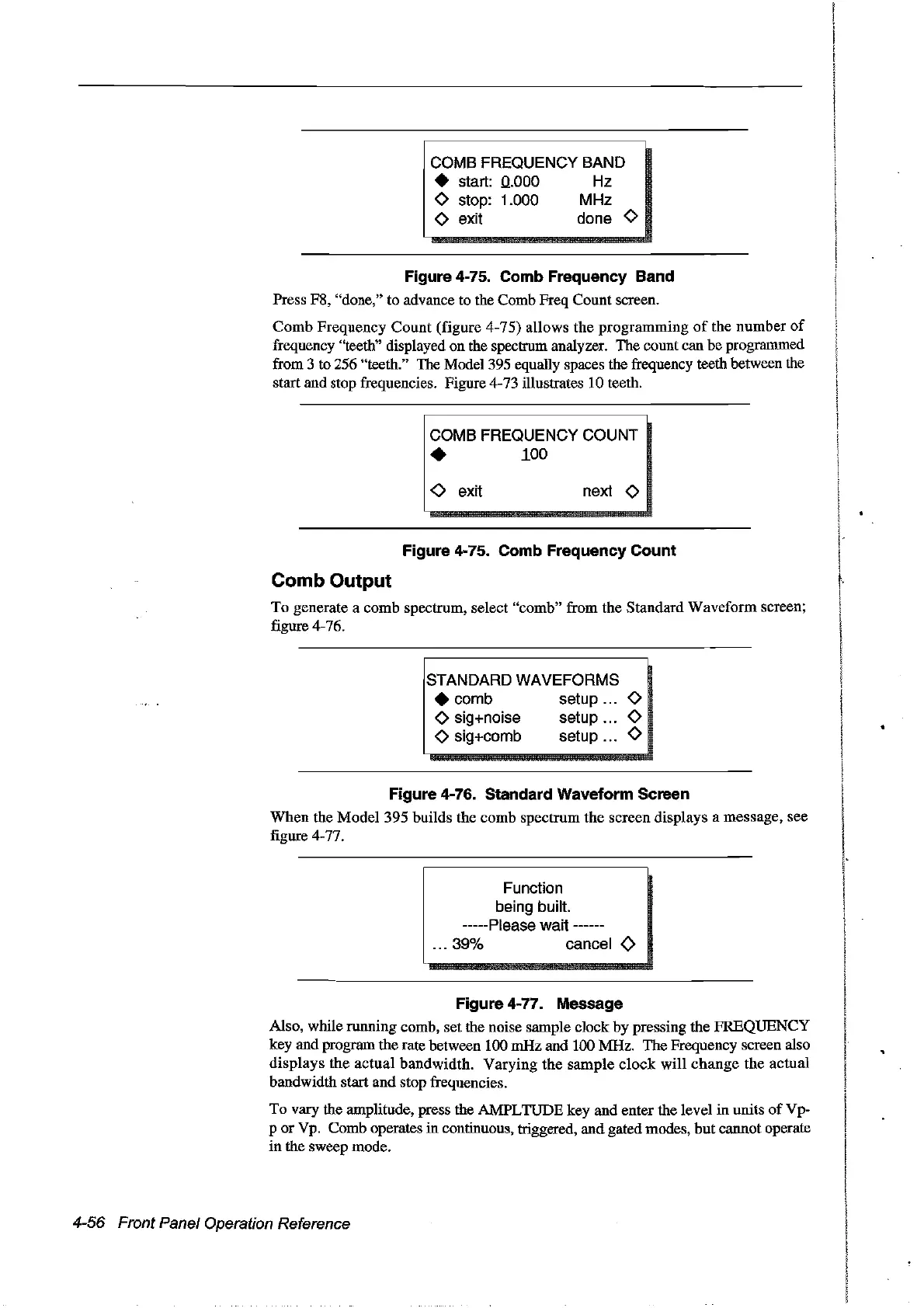
COMB FREOUENCY BAND
• start:
0..000
Hz
<>
stop: 1.000 MHz
<>
exit
do
ne
<>
Figure 4-75. Comb Frequeney Band
Press F8, "done," to advance to the Comb Freq Count screen.
Comb
Frequency Count (figure 4-75) allows the programming
of
the number
of
frequency "teeth" displayed on the spectrum analyzer. The count can be programmed
from 3 to 256 "teeth." The Model395 equally spaces the frequency teeth between the
start and stop frequencies. Figure 4-73 illustrates 10 teeth.
COMB FREOUENCY COUNT
•
100
<>
exit
next
<>
Figure 4-75. Comb Frequeney Count
Comb Output
To generate a comb spectrum, select "comb" from the Standard Waveform screen;
figure 4-76.
STANDARD WAVEFORMS
• comb setup
<>
<>
sig+noise setup
<>
<>
sig+comb setup
<>
Figure 4-76. Standard Waveform Sereen
Wben
the Model 395 builds the comb spectrum the screen displays a message, see
figure 4-77.
Function
being built.
-----Please wait ------
... 39% cancel
<>
Figure 4-77. Message
Also, while running comb, set the noise sample clock by pressing the FREQUENCY
key and program the rate between 100 mHz and 100 MHz. The Frequency screen also
displays the actual bandwidth. Varying the
sample
dock
will
change
the actual
bandwidth start and stop frequencies.
To vary the amplitude, press the AMPLTUDE key and enter the level in units
ofVp-
p or Vp. Comb operates in continuous, triggered, and gated modes, but cannot operate
in the sweep mode.
4-56 Front Panel Operation Reference
Artisan Technology Group - Quality Instrumentation ... Guaranteed | (888) 88-SOURCE | www.artisantg.com