1
MARKer
1 The rectangular box contains command
and
subsystem
keywords
with
their abbreviation
in
capitalletters.
@)The
oval "boxes" contain parameters;
shaded
boxes
are
de-
fault. The angle brackets
« » contain
user
entered parameters.
o The
circ1e
enc10ses punctuation ("sp" implies whitespace).
~
The arrow shows the command direction flow. The flow is
usually from left to right,
but
the command
may
contain loops flowing
in
other directions.
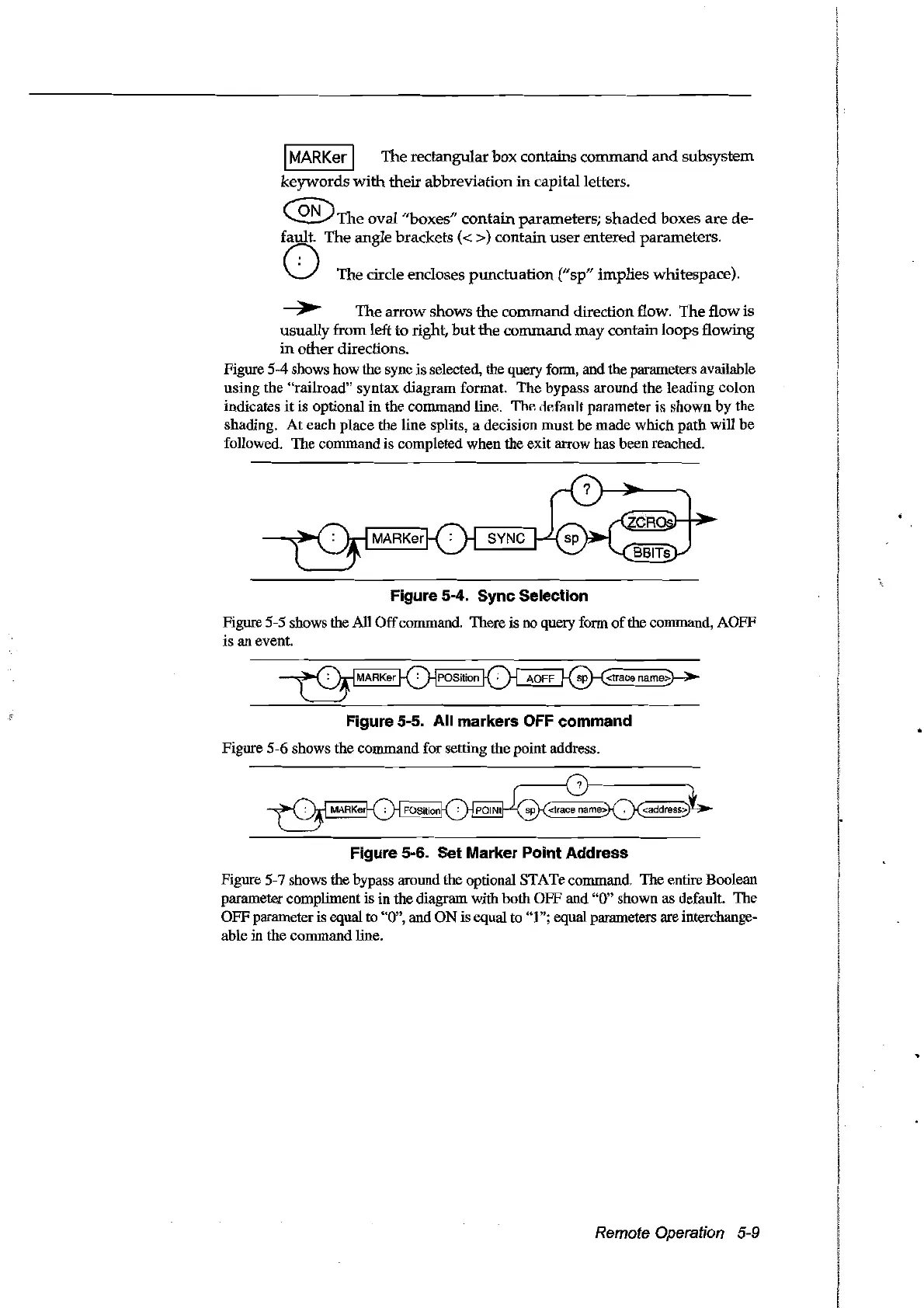
Figure 5-4 shows how the sync is selected, the query form, and the parameters available
using the "railroad" syntax diagram format.
The
bypass around the leading colon
indicates
it
is optional in the command line,
ThF.
ilF.ffllJlt
parameter
il>
shown
by
the
shading.
At
each
place the line splits, a decision
must
be
made
which
path
will be
followed. The command is completed when the exit arrow has been reached.
Figure 5-4. Sync Selection
Figure 5-5 shows the AlI
Off
commando There is no query form
of
the command, AOFF
is an event.
Figure 5-5. Ali markers OFF command
Figure 5-6 shows the command for setting the point address.
~:
Figure 5-6. Set Marker Point Address
Figure 5-7 shows the bypass around the optional STATe commando The entire Boolean
parameter compliment is in the diagram with both OFF and
"0" shown as default. The
OFFparameter is equal to
"0", and
ON
is equal to "1"; equal parameters are interchange-
able
in
the command line.
Remote Operation 5-9
Artisan Technology Group - Quality Instrumentation ... Guaranteed | (888) 88-SOURCE | www.artisantg.com