Standard RS-232 Connection
The Model 395 is configured as a
DCE
, and uses a 9-pin female connector (DB-9).
The
standard connection will he to a DTE ( generally a computer) with a standard 9-pin male
connector (DB-9). This connection
can
be
made using the 9-pin female
to
9-pin
male
cable (pIN 6001-00-0061) included with the Model 395.
If
the
DTE
uses a male DB-25,
the connection can
be
made using the 25-pin feroale to 9-pin male adapter (PIN
2100-
02-0328 ) included with the Mode1395. After connections are made, both the
Model395
and
the
DTE
must
be
configured to have the same baud rate and data format. The data
format for the model 395 is 8-bits,
no
parity,
one
stop bit. Refer to section 5.3 for
the
Model395
RS-232 setup.
Non-Standard RS-232 Connection
Because the Model 395 is configured as a DCE, connection
to
a device configured other
than
a standard
DTE
may
require a special cable.
Some
knowledge
of
the RS-232 is
beneficial
to
insuring a proper connection.
The
pin
assignments for
the
model 395 and
for a standard
DTE
(an
AT
comm
port),
are
given
in
Table
2-2.
ElA
STANDARD
RS-232-C specifies
the
electrical characteristics
and
pinouts
of
a
serial communication standard for connecting
"Data
Terminal
Equipment"
(DTE) to
"Data
Communication
Equipment"
(DCE).
A
DTE
is
usually
a
de
vice
such
as
a
terminal, computer,
or
printer, that is the final destination
of
data. A
DCE
is usually a
device
that
con
verts
data
to
another
forro
and
passes
it
through
such
as a
modem.
Because RS-232 signallines defined as outputs
on
a
DTE
are inputs on a
DCE
and vise
versa, connection
of
a
DTE
to
a
DTE
or
a
DCE
to
a
DCE
requires a special cable with
many
of
the lines interchanged. Generally a "Null Modem" cable will have the correct
linesinterchanged.
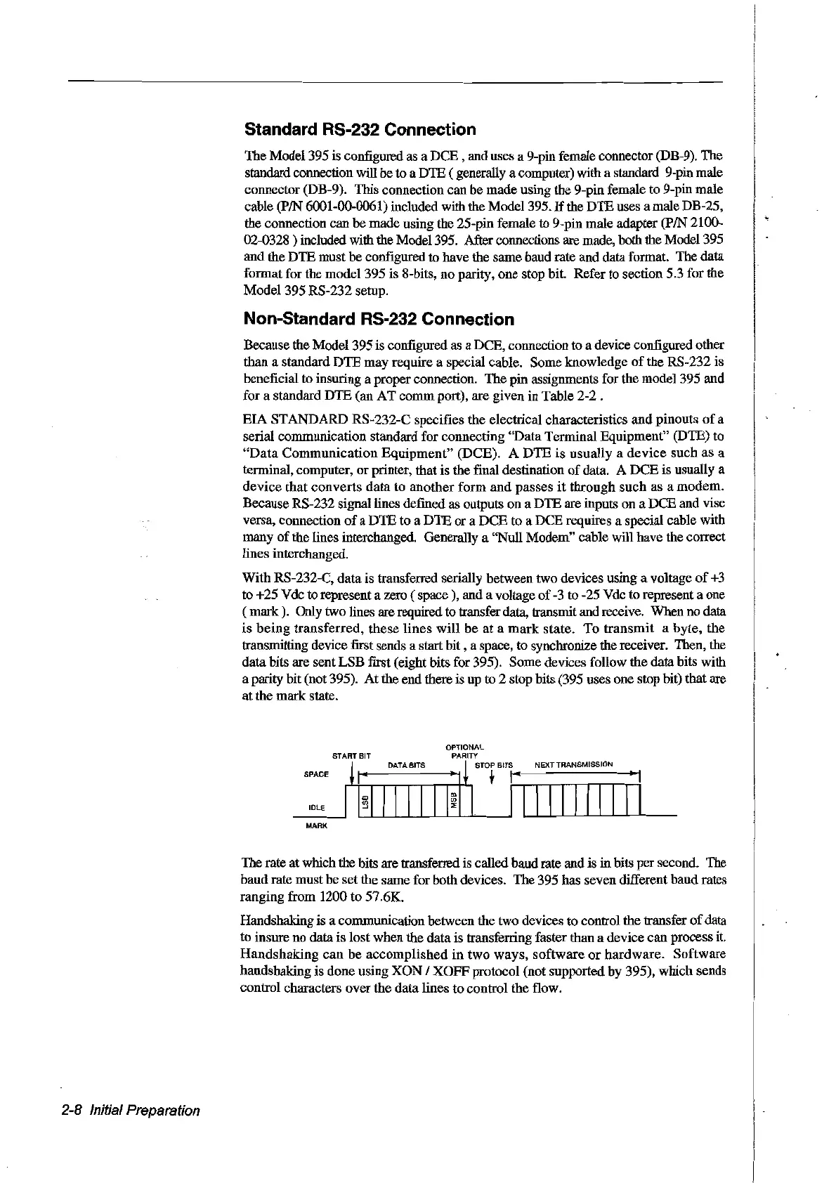
With
RS-232-C,
data
is transferred serially between two devices using a voltage
of
+3
to
+25
Vdc to represent a zero
(space),
and a voltage
of
-3 to -25 Vdc to represent a one
(
mark).
Only two lines are required to transfer data, transmit and receive. When no data
is
being
transferred,
these
Hnes
will
be
at
a
mark
state.
To
transmit
a
byte,
the
transmitting device
fust
sends a start
bit,
a space, to synchronize the receiver. Then, the
data
bits are sent
LSB
first (eight bits for 395). Sorne devices follow
the
data
bits with
a parity bit(not 395).
At
the end there is up
to
2 stop bits (395 uses
one
stop bit) that are
at
the
mark
state.
SPACE
IOLE
MARK
START BIT
DATA BITS
NEXT TRANSMISSION
2-8 Initial Preparation
The
rate at which the bits are transferred is called baudrate and is
in
bits
per
second. The
baud
rate
must
be
set
the same for both devices.
The
395 has seven different
baud
rates
ranging from 1200
to
57.6K.
Handshaking is a communication between the two devices to control the transfer
of
data
to insure no data
is
lost
when the
data
is transferring faster than a device
can
process
il.
Handshaking
can
be
accomplished
in
two
ways,
software
or
hardware.
Software
handshaking is done using
XON
1
XOFF
protocol (not supported by 395),
which
sends
control
characters
over
the
data
lines
to
control
the
flow.
Artisan Technology Group - Quality Instrumentation ... Guaranteed | (888) 88-SOURCE | www.artisantg.com