Foundry Configuration Guide for the FESX, FSX, and FWSX
7 - 38 © Foundry Networks, Inc. December 2005
Next, the following happens:
• Port3/Switch 2, the Designated port, sends an RST BPDU, with a proposal flag to Port3/Switch 3.
• Port2/Switch 2 also sends an RST BPDU with an agreed flag to Port2/Switch 1 and then places itself into a
forwarding state.
When Port2/Switch 1 receives the RST BPDU with an agreed flag sent by Port2/Switch 2, it puts that port into a
forwarding state. The topology is now fully converged.
When Port3/Switch 3 receives the RST BPDU that Port3/Switch 2 sent, 802.1W algorithm determines that these
RST BPDUs are superior to those that Port3/Switch 3 can transmit. Therefore, Port3/Switch 3 is given a new role,
that of an Alternate port. Port3/Switch 3 immediately enters a discarding state.
Now Port3/Switch 2 does not go into a forwarding state instantly like the Root port. It waits until the forward delay
timer expires twice on that port while it is still in a Designated role, before it can proceed to the forwarding state.
The wait, however, does not cause a denial of service, since the essential connectivity in the topology has already
been established.
When fully restored, the topology is the same as that shown on Figure 7.15.
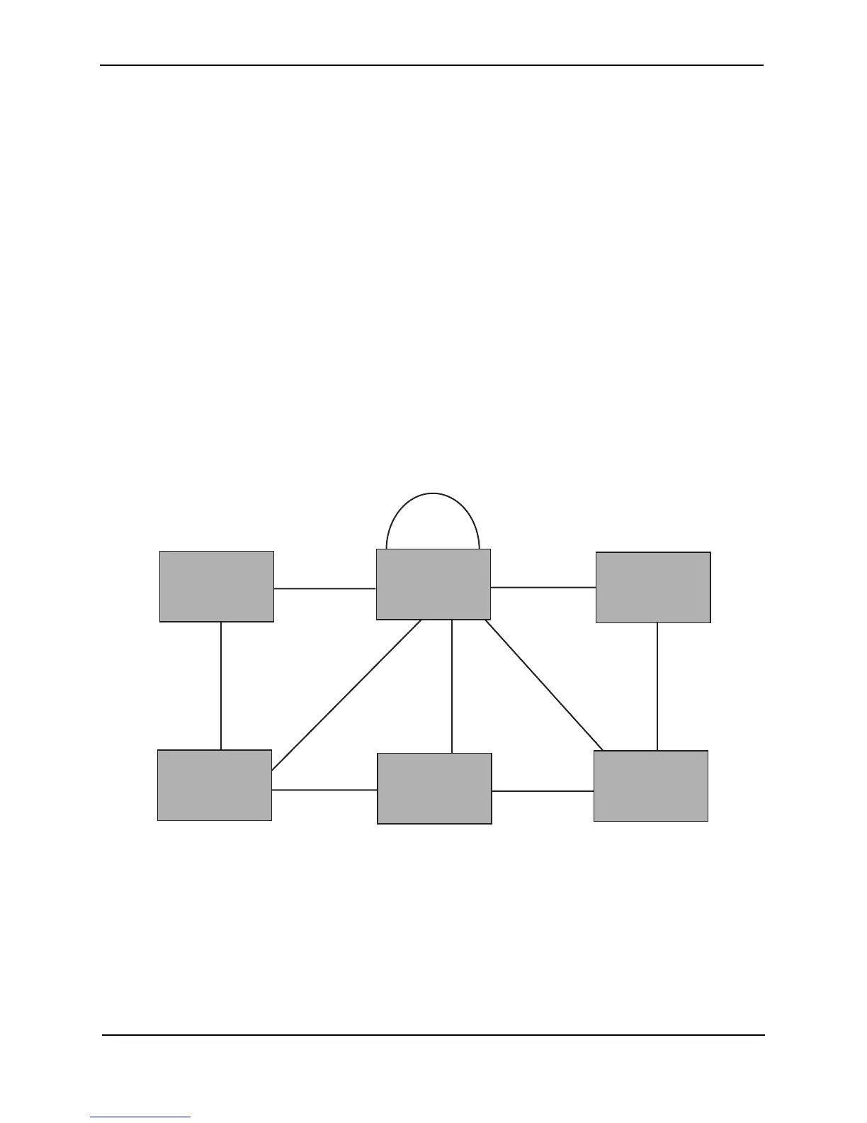
Convergence in a Complex 802.1W Topology
The following is an example of a complex 802.1W topology.
Figure 7.18 Complex 802.1W Topology
In Figure 7.18, Switch 5 is selected as the root bridge since it is the bridge with the highest priority. Lines in the
figure show the point-to-point connection to the bridges in the topology.
Switch 5 sends an RST BPDU that contains a proposal flag to Port5/Switch 2. When handshakes are completed in
Switch 5, Port5/Switch 2 is selected as the Root port on Switch 2. All other ports on Switch 2 are given Designated
port role with discarding states.
Port5/Switch 2 then sends an RST BPDU with an agreed flag to Switch 5 to confirm that it is the new Root port
and the port enters a forwarding state. Port7 and Port8 are informed of the identity of the new Root port. 802.1W
algorithm selects Port7 as the Designated port while Port8 becomes the Backup port.
Port2 Port2
Port7 Port8
Port3
Port3
Port4Port4
Port2
Port3
Bridge priority = 200
Bridge priority = 400
Bridge priority = 300
Bridge priority = 1000
Port4
Port5
Port3
Port3
Bridge priority = 900
Bridge priority = 60
Port2
Port5 Port5
Port4
Switch 2
Switch 1Switch 1
Switch 5
Switch 3
Switch 4
Switch 6