MPC5200B Users Guide, Rev. 1
2-72 Freescale Semiconductor
Pinout Tables
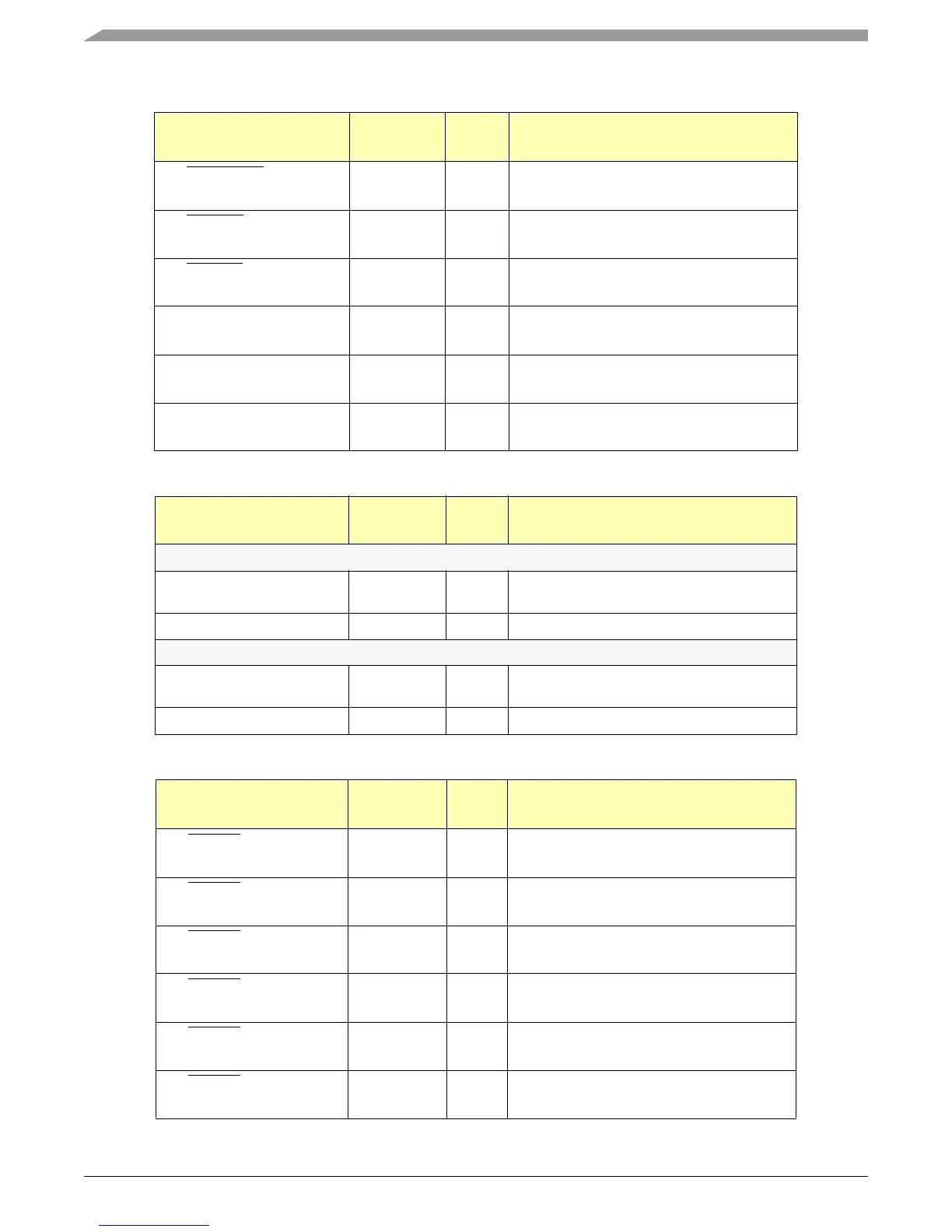
Table 2-29. CLOCK / RESET Pin Functions
CLOCK / RESET Functions
Reset
Value
Description
Pin PORRESET
Ball A13
logic 1 Power On Reset
Pin HRESET
Ball B13
logic 1 Hard Reset
Pin SRESET
Ball A14
logic 1 Soft Reset
Pin SYS_XTAL_IN
Ball A15
APLL Chip clock crystal / external clock input
Pin SYS_XTAL_OUT
Ball D14
clk APLL Chip Clock Crystal
Pin SYS_PLL_TPA
Ball B15
MPC5200B System Test Pll Output (analog
output)
Table 2-30. Dedicated GPIO Pin Function
DEDICATED GPIO Functions
Reset
Value
Description
Pin GPIO_WKUP_6 Ball C15
GPIO Wake_Up logic 0 Asynchronous GPIO with Wake_Up Capability
GPIO_WKUP_6
Memory Chip Select logic 0 SDRAM Chip Select 1
Pin GPIO_WKUP_7 Ball C12
GPIO Wake_Up hi - z Asynchronous GPIO with Wake_Up Capability
GPIO_WKUP_7
LocalPlus MOST/Graphics TSIZ hi - z TSIZ1 for LocalPlus MOST/GRAPHICS mode
Table 2-31. Systems Integration Unit Pin Functions
SYSTEMS INTEGRATION
UNIT
Functions
Reset
Value
Descriptions
Pin LP_CS0
Ball W14
logic 1 LocalPlus Bus Chip Select 0
Pin LP_CS1
Ball Y14
logic 1 LocalPlus Bus Chip Select 1
Pin LP_CS2
Ball V15
logic 1 LocalPlus Bus Chip Select 2
Pin LP_CS3
Ball W15
logic 1 LocalPlus Bus Chip Select 3
Pin LP_CS4
Ball Y15
logic 1 LocalPlus Bus Chip Select 4
Pin LP_CS5
Ball V16
logic 1 LocalPlus Bus Chip Select 5