GE HealthCare CONFIDENTIAL
DIRECTION 5936427, REV. 1 LOGIQ TOTUS Basic Service Manual
Section 8-10 - Replacing Back End Parts 8 - 177
8-10-5 Replacement of the GPU Set-T
This table includes information specific to these instructions. For more information 8-2-6 "Tools needed
for servicing the LOGIQ Totus" on page 8-5 /8-2-7 "PPE Required During Service" on page 8-6.
8-10-5-1 Preparations
1.) Power off/Shutdown the system as described in 1-7-2 "Lockout/tagout procedure" on page 1-25
2.) Remove the Rear Cover Mid Assy-T as described in 8-8-10 "Replacement of the Rear Cover Mid
Assy-T" on page 8-138
3.) Remove the Rear Cover Top Assy-U as described in 8-8-15 "Replacement of the Rear Cover Top
Assy-U" on page 8-143
8-10-5-2 Removal Procedure
8-10-5-3 Installation Procedure
1.) Parts to be installed in reverse order of removal
2.) Perform “Functional Checks after FRU replacement (Debrief Guideline)” as described in Section 8-
12 on page 8-223
Table 8-94 Manpower, Time, Tools, and PPE
Manpower Time Tools PPE
One person Approximately 15 minutes Phillips screwdriver
Cut resistant gloves
Knee Pad
Steps Corresponding Graphic
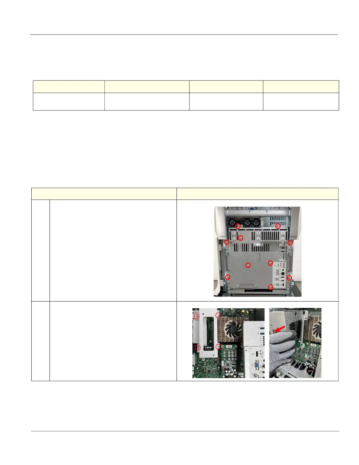
1. Unscrew 10 screws to remove the Unity Rear Shield
Brkt from the console.
Note: If the WLAN-T was installed, remove the
WLAN-T as described in
8-11-13 "Replacement of
the WLAN-T and WLAN USB A Cable" on page
8-199
2. Unscrew 4 screws to remove the GPU Set-T.
 Loading...


