GE HEALTHCAREDRAFT VOLUSON® P8 / VOLUSON® P6
DIRECTION 5459672-100, R
EVISION 6 DRAFT (JANUARY 17, 2013) PROPRIETARY SERVICE MANUAL
Chapter 3 - Setup Instructions 3-63
3-8-4-1 External I/O Pin Outs (cont’d)
Section 3-9
Available Probes
See Chapter 9 - Probes, on page 9-15, for part numbers to be used when ordering new or replacement
service probes.
Section 3-10
Software/Option Configuration
For description refer to:
• Section 3-8-1 "System Setup" on page 3-54 and
• Section 3-8-2 "Measure Setup" on page 3-59
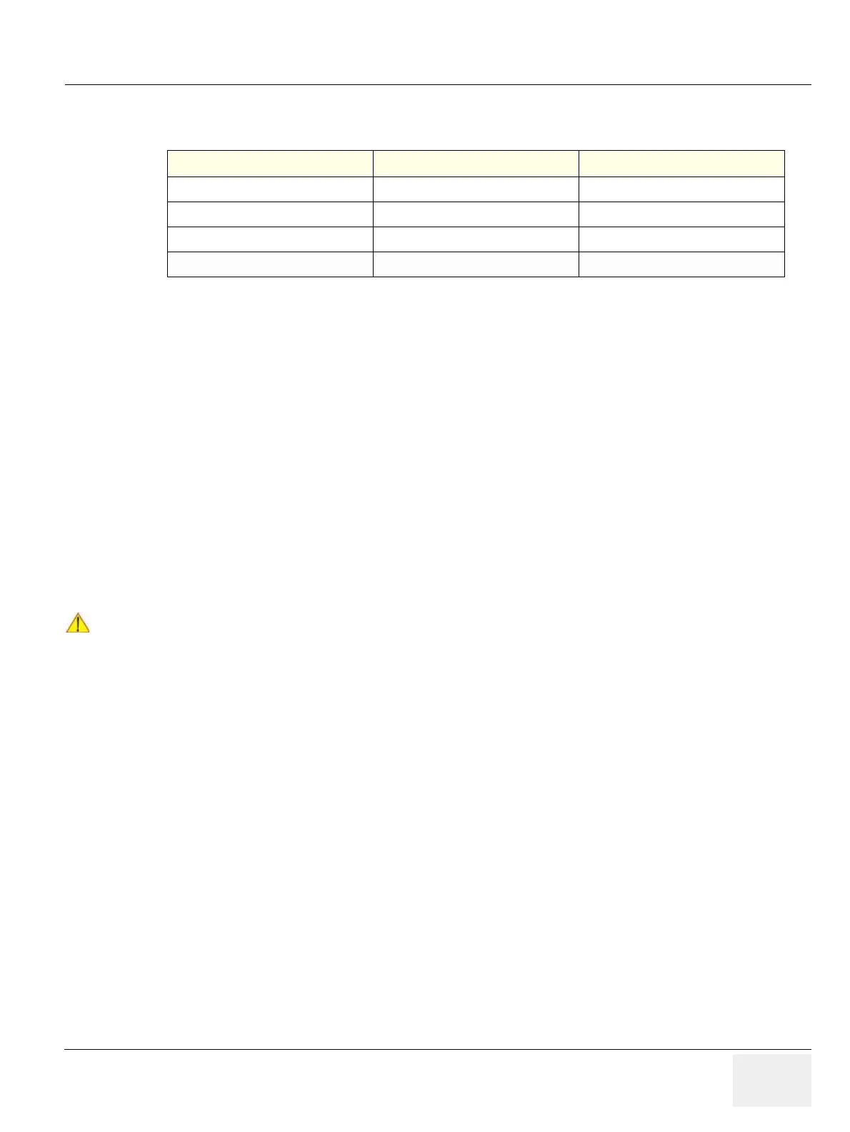
Table 3-13 USB Connectors
Pin No Output Signal Description
1 VCC USB Power Supply
2 - Data USB Data (-)
3 + Data USB Data (+)
4 GND USB Power Ground
NOTICE
!! NOTICE:
More detailed information pertaining System Setup and Measure Setup adjustments is found in the
Voluson® P8 / Voluson® P6 Basic User Manual, which is available in different languages.