EasyManuals Logo

GE Voluson P6 Service Manual

GE Voluson P6
553 pages
To Next Page IconTo Next Page
To Previous Page IconTo Previous Page
Page #435 background imageLoading...
Page #435 background image
GE HEALTHCARERAFT VOLUSON® P8 / VOLUSON® P6
DIRECTION 5459672-100, R
EVISION 6 DRAFT (JANUARY 17, 2013) PROPRIETARY SERVICE MANUAL
8-72 Section 8-32 - Replacement of the BF64
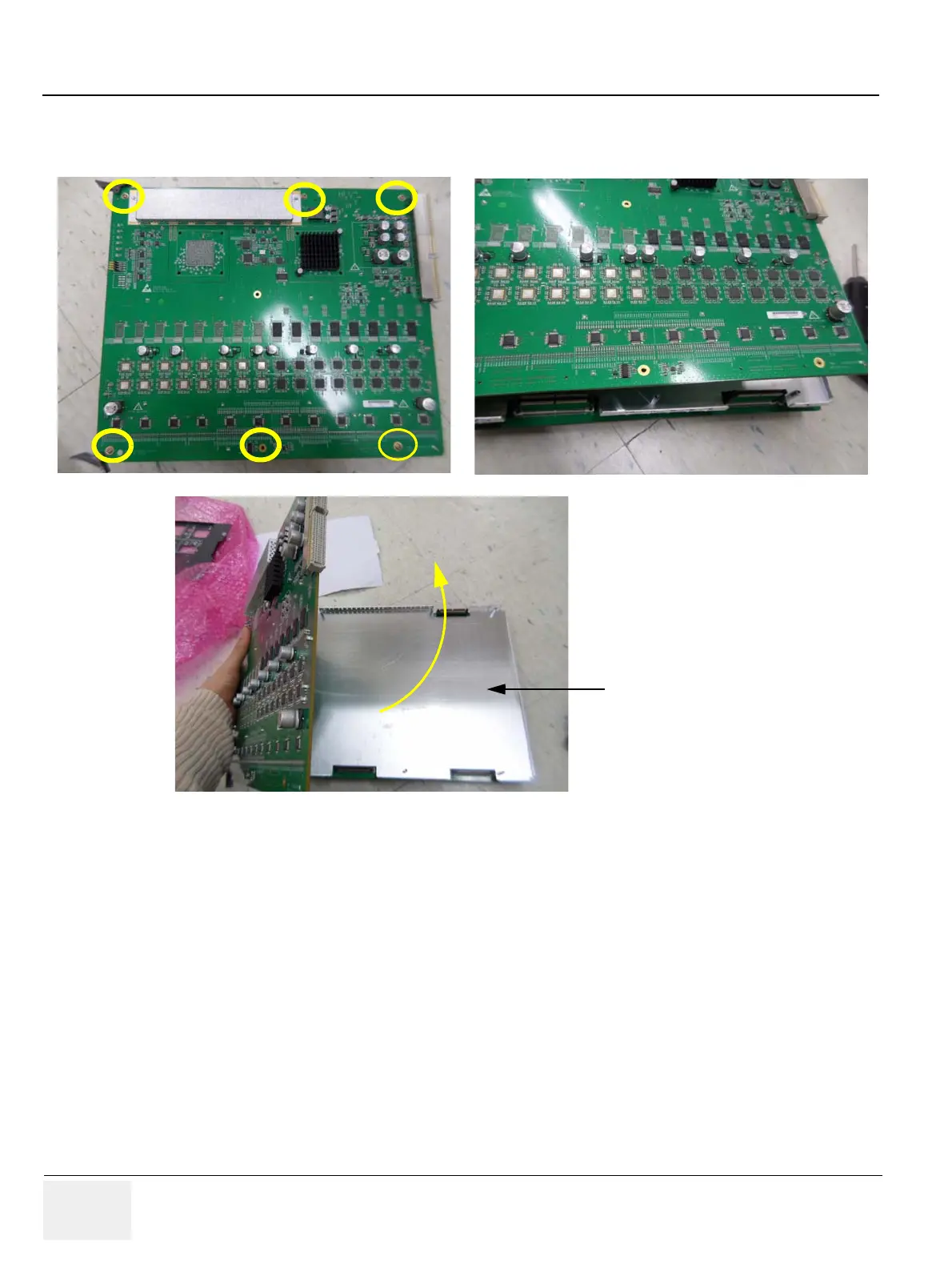
2.) Unscrew 6 screws.
3.) Remove BF64 from the EMI Shield cover..
8-32-4 Installation Procedure
1.) Install the new parts in the reverse order of removal.
2.) Perform: FRU8-33: Replacement of the BF64 - Functional Tests..
Figure 8-85 Unscrewing 6 screws
EMI Shield cover

Table of Contents

Other manuals for GE Voluson P6

Questions and Answers:

Question and Answer IconNeed help?

Do you have a question about the GE Voluson P6 and is the answer not in the manual?

GE Voluson P6 Specifications

General IconGeneral
Transducer Ports3
3D/4D ImagingYes
Power Requirements100-240 VAC, 50/60 Hz
Storage Temperature-20°C to 60°C
ApplicationObstetrics, Gynecology
Imaging ModesColor Doppler, Power Doppler
Probe TypesConvex, Linear, Endocavity, Phased Array
Operating Temperature10°C to 40°C
Humidity Range30% to 80%
Transducer Optionsendocavity probes

Related product manuals