GE HEALTHCAREDRAFT VOLUSON® P8 / VOLUSON® P6
DIRECTION 5459672-100, R
EVISION 6 DRAFT (JANUARY 17, 2013) PROPRIETARY SERVICE MANUAL
Chapter 5 - Components and Functions (Theory) 5-23
5-3-3 RFS - Radio Frequency interface and System controller
5-3-3-1 RFS board - FPGA
A.) Beamformer interface
• LVDS-interface
• Raw ultrasound data is transferred from the Beamformer to the Interface FPGA.
• Configuration data (Probe Setup data, Beam Setup data) is transferred from the Interface FPGA to
the Beamformer.
• FPGA configuration data is transferred from the Interface FPGA to the Beamformer
B.) DMA Logic
• Receives pre-processed ultrasound data coming from the Processing FPGA.
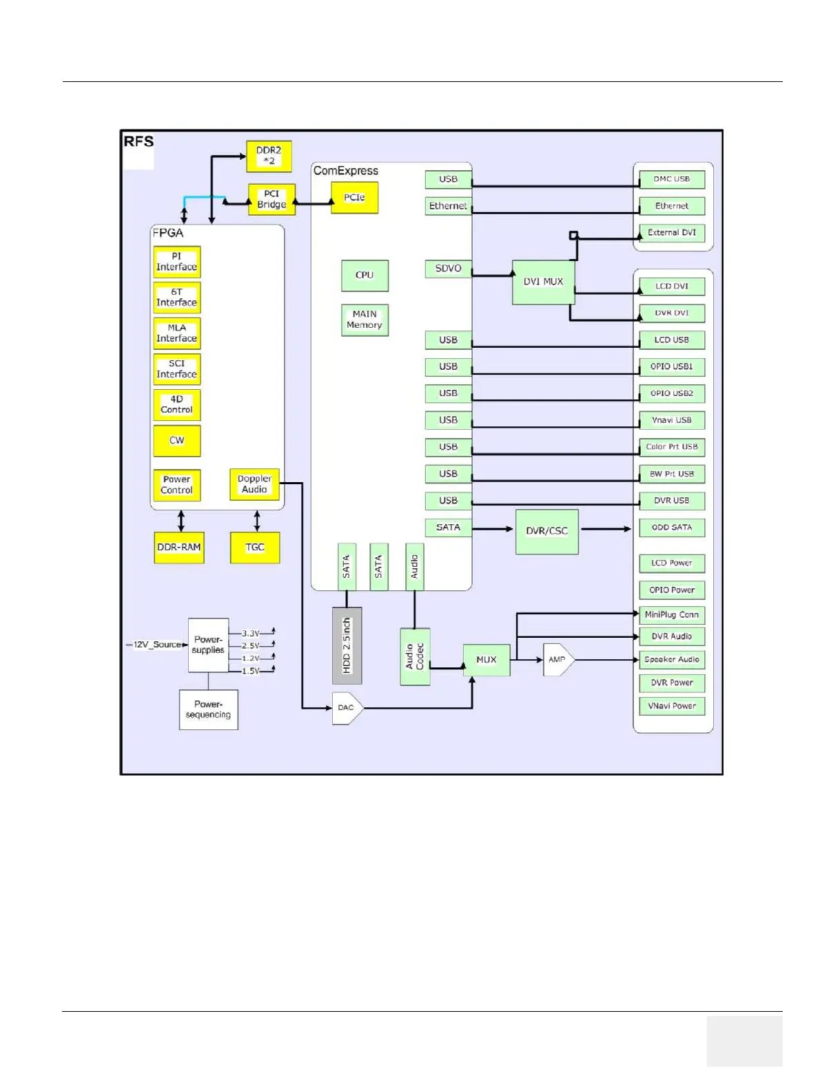
Figure 5-9 RFS-Board - Block diagram