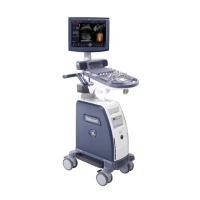
GE HEALTHCARERAFT VOLUSON® P8 / VOLUSON® P6
DIRECTION 5459672-100, R
EVISION 6 DRAFT (JANUARY 17, 2013) PROPRIETARY SERVICE MANUAL
8-88 Section 8-41 - Replacing optional Peripherals
Section 8-41
Replacing optional Peripherals
8-41-1 Manpower
One person, 70 minutes
8-41-2 Tools
Standard Field Service Tool Kit
8-41-3 Printer Installation (BW and Color)
8-41-3-1 BW Printer: SONY UP-D897, Color Printer: SONY UP-D25MD
1.) Assemble 2 EMI gaskets (5448934 - EMI gasket, side, b-w printer bkt-3) on printer base plate.
2.) Assemble 2 EMI gaskets (5447303 - EMI gasket, side, b-w printer bkt-2) on printer base plate.
3.) Assemble 2 EMI gaskets (5457475 - EMI gasket, side, b-w printer bkt-1) on printer base plate.
4.) Assemble printer base pate with B/W printer using 8 screws (2306562-screw FH M3 x 6).
NOTICE
!! NOTICE:
Normally auxiliary devices and peripherals come pre-installed with the Voluson® P8 / Voluson® P6
system.
NOTICE
!! NOTICE:
READ and UNDERSTAND these instructions thoroughly before proceeding with the installation.
Perform each step in sequence and check it off when completed. If a problem occurs after completion,
go back through the procedure and check for implementation errors before contacting your Ultrasound
Region.
CAUTION
!! CAUTION:
Possible Operational damage. Failure to strictly follow ESD (Electrostatic Discharge)
precautions during this installation may cause constant or intermittent operational
abnormalities. Strictly follow all precautions.
 Loading...
