GE HEALTHCARERAFT VOLUSON® P8 / VOLUSON® P6
DIRECTION 5459672-100, R
EVISION 6 DRAFT (JANUARY 17, 2013) PROPRIETARY SERVICE MANUAL
5-42 Section 5-10 - Power Distribution
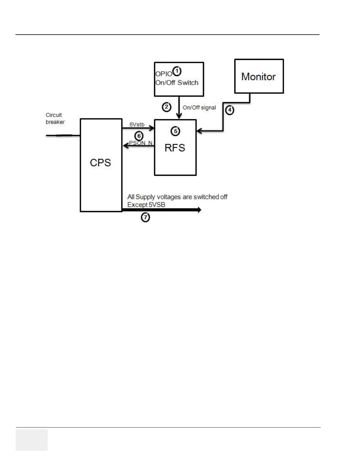
5-10-1-3-2 Power Down Sequence Description
1.) On/Off Switch is pressed on OPIO.
2.) ON/OFF signal is sent from On/Off Switch via OPIO cable to RFS
3.) “Shut down” dialog comes up and “Shut down” signal is sent.
4.) PC “Shut down” sequence is started in RFS.
5.) At the end of this sequence RFS sends PS_ON Signal to CPS.
6.) CPS shuts down all Supply voltages except Standby voltage (5VSB).
5-10-1-4 Mechanical Concept and Overview
The AC Power’s main tasks are to supply the internal subsystems with AC power. To reduce inrush
current, an inrush current limiter is implemented.
Voltage to peripherals are provided from input without configuration.
From the Mains Power Input module, the AC power is routed via an Inrush Current Limiter to an internal
ACDC module.
5-10-1-5 Functions of ACFE
• Inrush Current limiter
• Switch the peripheral power
Figure 5-22 Power Down Sequence