GE HEALTHCARERAFT VOLUSON® P8 / VOLUSON® P6
DIRECTION 5459672-100, R
EVISION 6 DRAFT (JANUARY 17, 2013) PROPRIETARY SERVICE MANUAL
8-32 Section 8-13 - Remove the Pedestal Bottom Cover
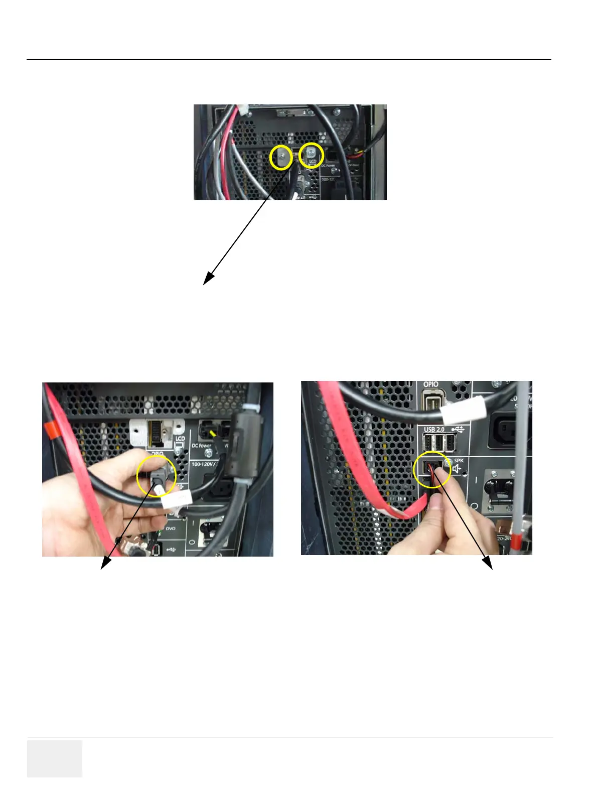
8.) Unscrew 2 screws to remove the MONITOR CABLE BRACKET. Then unscrew the screw of MAIN
PANEL LONG CABLE and disconnect the CABLE. Refer to the figure below.
9.) Disconnect other 2 cables. (OPIO PANEL CABLE, VS SPEAKER CABLE ASSY). Refer to the
figure below.
8-13-1 Installation Procedure
1.) Install the new parts in the reverse order of removal.
2.) Perform: FRU8-12: Remove the Pedestal Bottom Cover - Functional Tests.
Figure 8-36 Unscrewing 2 screws and remove the MONITOR CABLE BRACKET
Figure 8-37 Disconnecting 2 CABLES
MONITOR CABLE BRACKET
OP PANEL CABLE
VS SPEAKER CABLE ASSY