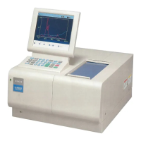
5 - 5
5.3 Configuration of ISE Hardware
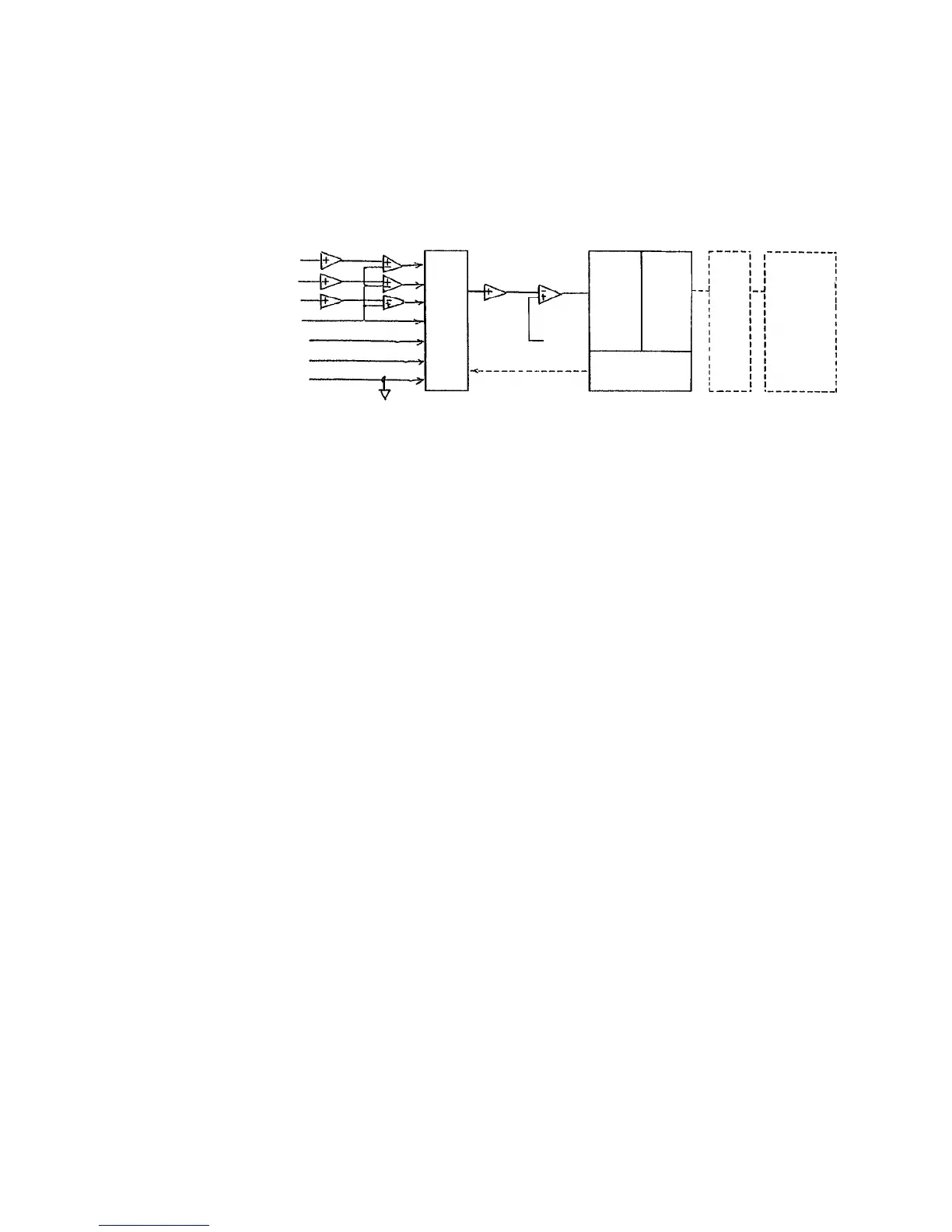
(1) The ADC controller converts the analog values of the ISE electrodes and reference
voltages (V2/V8/V0) to digital ones upon receiving an instruction from the application via
the driver and stores the digital values into the DPRAM (dual port RAM). The values are
taken into the application via the driver.
(2) The application accesses the driver, but does not control the ADC directly.
(3) ADC input value Vout is as follows.
(a) When MPX selects Na electrode Vout = -20 × (Vn - Vr) + Vos [mV]
(b) When MPX selects K electrode Vout = -20 × (Vk - Vr) + Vos [mV]
(c) When MPX selects Cl electrode Vout = 20 × (Vcl - Vr) + Vos [mV]
(d) When MPX selects Ref electrode Vout = -Vr + Vos [mV]
(e) When MPX selects reference voltage (V2) Vout = 2,000 ± 5 [mV]
(f) When MPX selects reference voltage (V8) Vout = 8,000 ± 5 [mV]
(g) When MPX selects reference voltage (V0) Vout =Vos [mV]
NOTES: 1. The unit is mV.
2. Each AMP offset voltage is included in Vos.
3. With the 902, Vos is 110 mV.
Na electrode (Vn)
K electrode (Vk)
Cl electrode (Vc)
Ref electrode (Vr)
Reference voltage (V2)
Reference voltage (V8)
Reference voltage (V0)
ISE Hardware Configuration
AMP AMP
(G = 1) (G = 20)
MPX
AMP AMP
(G = 1) (G = 1)
ADC control Software
ADC DPRAM
ADC controller
Driver
Application
Vos
Vout