16 - 50
16.9.5 Current Loop
Current loop is selected by turning on the switch No. 1 on the PC board. In the current loop
mode, the J402 connector is used as in the RS-232C mode.
(1) Connection Diagram
Refer to (4) in 16.9.2.
(2) Connecting Cable
The J402 connector side uses a 15-pin interface connector (female) of type RDAD-15S.
The cable side should use the following.
HDAB-15P (made by Hirose Denki) or equivalent
(3) Pin Arrangement
Refer to (3) in 16.9.2.
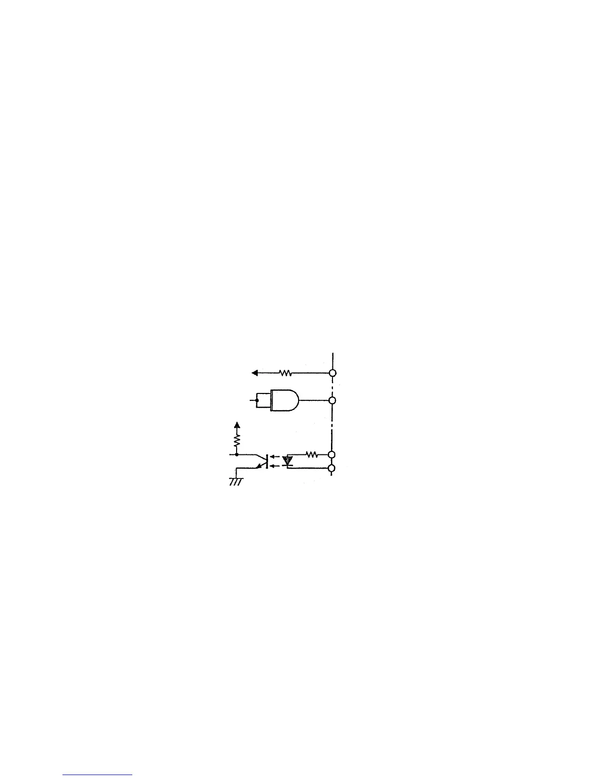
(4) Signal Input Circuit
16.9.6 Communication Monitor
Data transferred between the Model 902 and host can be monitored by connecting a personal
computer or other monitor to J405 on the RSDIST board.
For monitoring, turn off the switch No. 1 on the PC board.
(1) Connection Diagram
Refer to (4) in 16.9.2.
(2) Connecting Cable
The J405 connector side of RSDIST board is a 25-pin interface connector (female) of type
SDBB-25S. The cable side should use the following.
HDBB-25P (made by Hirose Denki) or equivalent
Model 902 side Host side
150 Ω
75452
33 Ω
470 Ω
+5 V