15 - 17
+5 V
Red
GND
Black
+
5 4 3 2 1
9 8 7 6
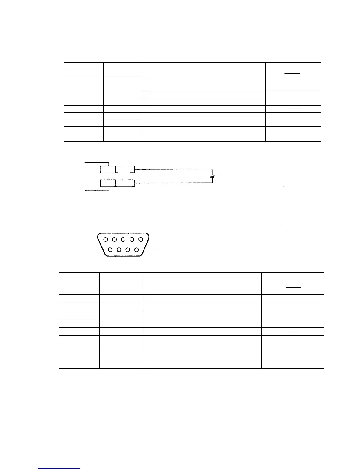
•• Wiring
Wire Color Symbol Description Signal Direction
Shield FG Frame ground
Purple SD (TXD) RS-232C data transmission Output
Brown RD (RXD) RS-232C data reception Input
Pink RS (RTS) RS-232C request to send Output
Blue CS (CTS) RS-232C clear to send Input
Black GND (SG) Ground (common ground with each signal)
Yellow TIM Timing input Input
White OK OK output Output
Gray NG NG output Output
Red +5 V +5 V power input Input
•• Pin Arrangement
D-sub 9 pins (female)
DTE specifications (terminal definition)
#4-40 screw (male)
Pin No. Symbol Description Signal Direction
Connector
case
FG Frame ground
1 TIM Timing input Input
2 RD (RXD) RS-232C data reception Input
3 SD (TXD) RS-232C data transmission Output
4 OK OK Output
5 GND (SG) Ground (common ground with each signal)
6 NG NG Output
7 RS (RTS) RS-232C request to send Output
8 CS (CTS) RS-232C clear to send Input
9 +5 V +5 V power supply Input
5 V DC
 Loading...