Model IFP-2000/ECS Installation Manual 151430-L8
7-5
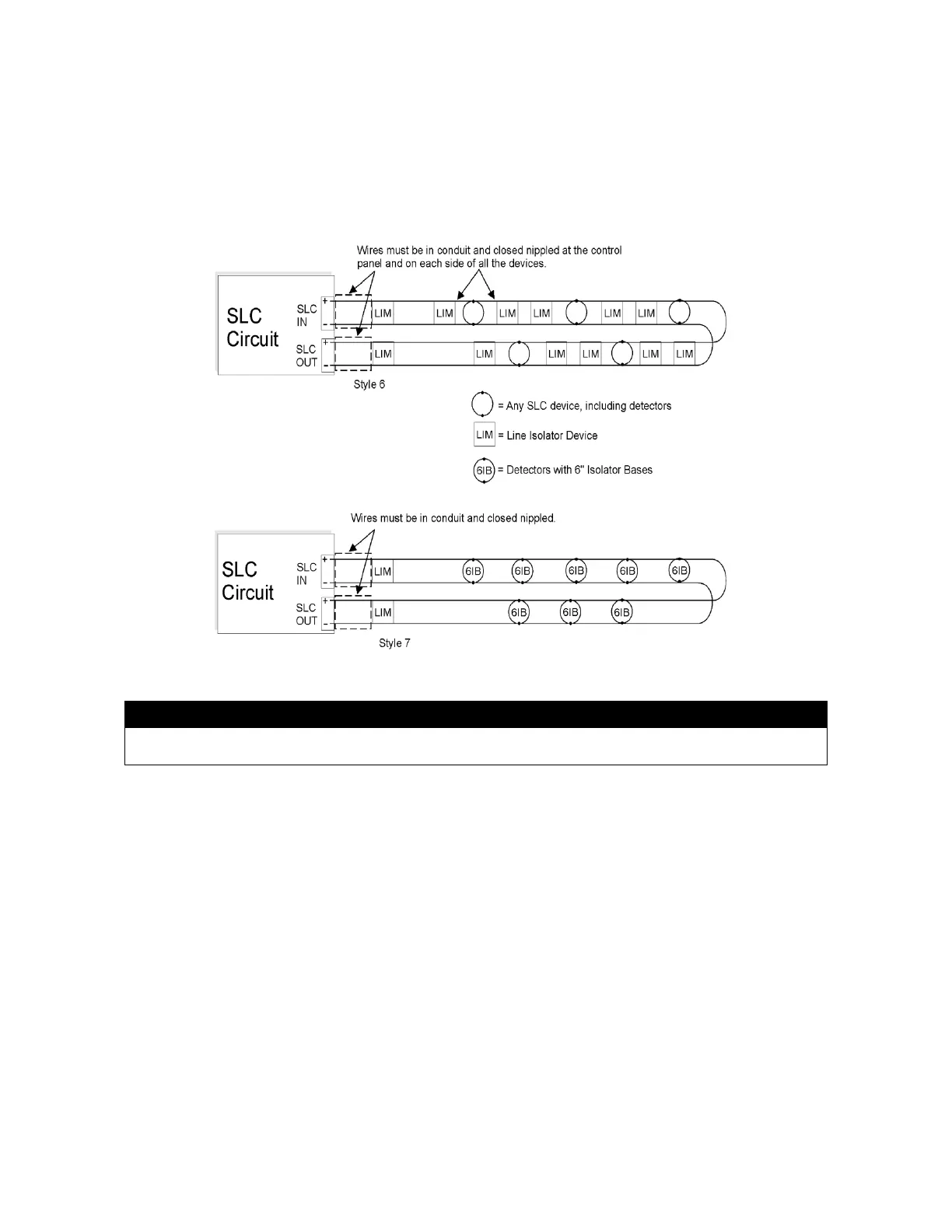
7.4.2 Wiring 5815XL in Style 6 & 7 (Class A) Configuration
Figure 7-3 on page 5 illustrates how to wire the SLC loop for Style 6 or Style 7 Class A installations.
Note: Style 6 does not use short circuit isolator devices
Note: Style 7 requires an isolator module as the first device on the in and the out loops.
Note: No t-taps allowed on Class A SLC loops
Figure 7-3 Class A SLC Configuration
Caution
For proper system supervision do not use looped wire under terminals marked SLC + and – of the SLC device connectors.
Break wire runs to provide supervision of connections.
 Loading...

