151430-L8 Control Panel Installation
4-26
2. Configure the circuit through programming (see Section 9.5).
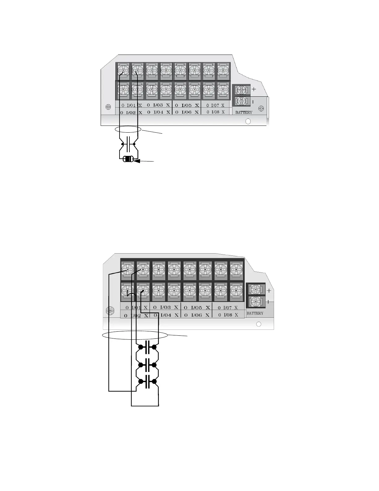
Figure 4-34 Class B Input Switches
4.12.2.2 Class A Inputs
You can connect conventional Class A switches, such as waterflow switches and pull stations, directly to the
Flexput circuits of the control panel.
To install a Class A switch:
1. Wire the Class A switch as shown in Figure 4-35.
2. Configure the circuit through programming (see Section 9.5).
Figure 4-35 Class A initiating Switches
Note: In programming any point that uses multiple Flexput circuits, the lowest Flexput circuit number is used to
refer to the circuit pair. For example, Figure 4-35 uses both Flexput circuit 1 and 2, so in programming it
would be referred to as point 1.
supervised
power limited
Maximum Impedance
per circuit is 50
UL Listed EOL 4.7 k
Note:
Flexput circuit 1 and 2
used as an example.
Any Flexput point pairing
could be used.
supervised
power limited
Maximum Impedance per circuit
is 50
 Loading...

