151430-L8 Networking
5-8
5.5 Using Both Repeaters and Direct Connect
Wiring on a Networked System
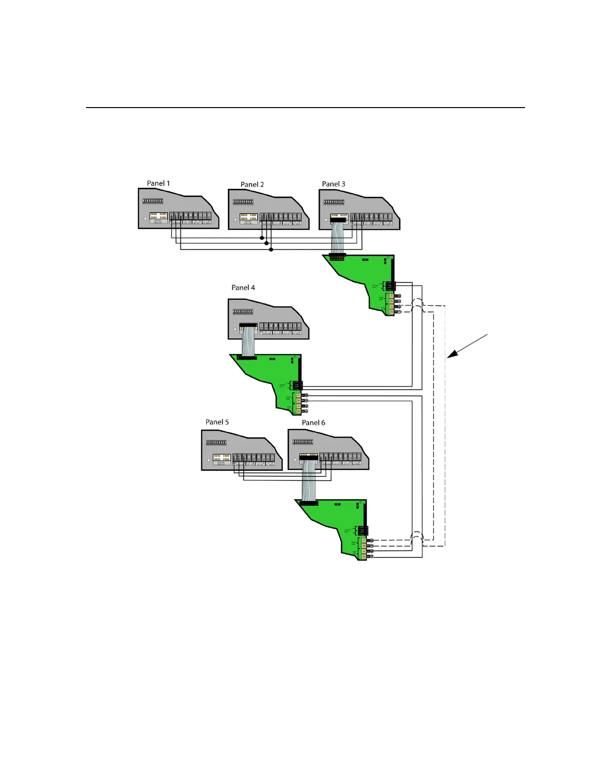
Figure 5-9 on page 8 below shows a network wiring example using both repeaters and direct connect wiring. All
repeaters in the system must be placed only on panels that are at the ends of a direct connect BUS or connected to
panels with no direct connect network wiring.
Figure 5-9 Network Wiring Example Using Both Repeaters and Direct Connect Wiring
5.5.1 Setting the Network Terminators at Panel DIP Switches and
Repeater Jumpers
Use the following steps for determining DIP switch and jumper settings.
1. DIP switch positions 8 through 10 on the control panel are used for direct connect network BUS termination.
When a panel is located at the end of a direct connect BUS and it does NOT have a repeater connected, DIP
switches 8, 9 and 10 must be ON. When a panel is not direct connected to other panels, but a repeater is used
 Loading...

