151430-L8 Control Panel Installation
4-24
2. Configure the circuit through programming (see Section 9.5)
Figure 4-32 Class B Notification Appliance Circuit Wiring
Maximum voltage drop is 3V per Class B notification. See Table 4-3.
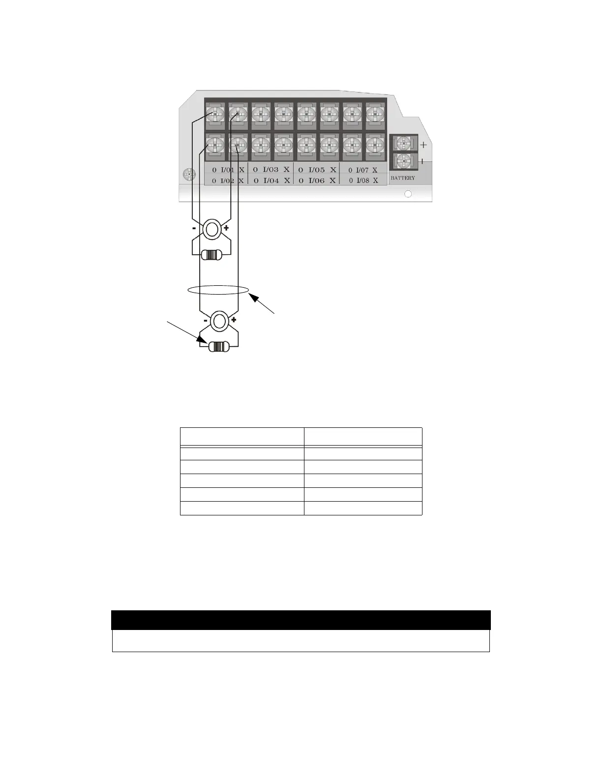
4.12.1.2 Class A Notification Wiring
You must use an appliance from the list of compatible appliances in Appendix A at the back of this manual.
To install a Class A notification appliance circuit:
1. Wire the Class A notification appliances as shown in Figure 4-33.
Table 4-3: Maximum Impedance Class B
Current Maximum Impedance
1.0A 3
1.5A 2
2.0A 1.5
2.5A 1.2
3.0A 1.0
Caution
For proper system supervision do not use looped wire under terminals marked O and X of the Flexput
connectors. Break wire runs to provide supervision of connections.
supervised
power limited
Notification Wiring
Regulated 24 VDC
3A per circuit, 9A max combined
UL Listed EOL
4.7 k
Alarm Polarity Shown
 Loading...

