151430-L8 Control Panel Installation
4-30
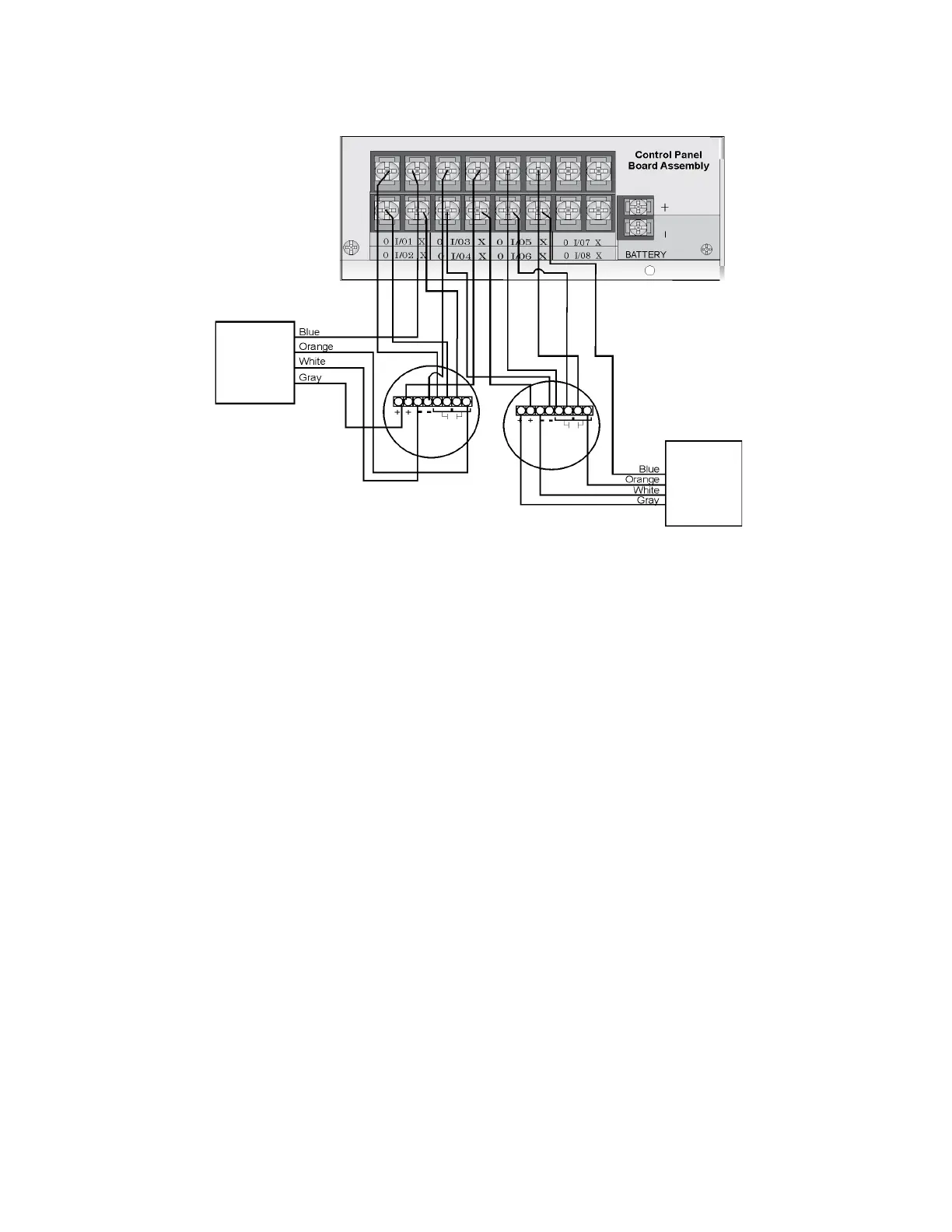
2. Smoke power is supplied to each Class A loop as shown in Figure 4-39.
Figure 4-39 Class A 4-Wire Smoke Detector Connections
Note: In programming any point that uses multiple Flexput circuits are always referred to as the lowest Flexput
circuit number used. For example, Figure 4-39 uses Flexput circuits 1, 2, 3 together and 4, 5, 6 together.
In programming (1, 2, 3) would be referred to as point 1, and (4, 5, 6) would be referred to as point 4.
4.12.5 Auxiliary Power Installation
Flexput Circuits 1-8 on the control panel can be used as auxiliary power circuits. The three types of auxiliary
power available are:
• Door Holder Power (see Section 4.12.5.1)
• Constant Power (see Section 4.12.5.2)
• Resettable Power (see Section 4.12.5.3)
• Sounder Sync Power (see Section 4.12.5.4)
Auxiliary power circuits are power limited. Each circuit can source up to 3A (total current for all Flexput circuits
must not exceed 9.0 A in alarm, and 6A when used as constant auxiliary power in normal standby).
To install an auxiliary power circuit:
1. Wire the Flexput circuit(s) that will be used for auxiliary power. See Figure 4-40 for location of Flexput cir-
cuits.
Air Products
PAM-2
Model 160150
Supervision
Module
Air Products
PAM-2
Model 160150
Supervision
Module
Supervised
Power Limited
maximum
impedance per
circuit is 50
 Loading...

