Model IFP-2000/ECS Installation Manual 151430-L8
3-7
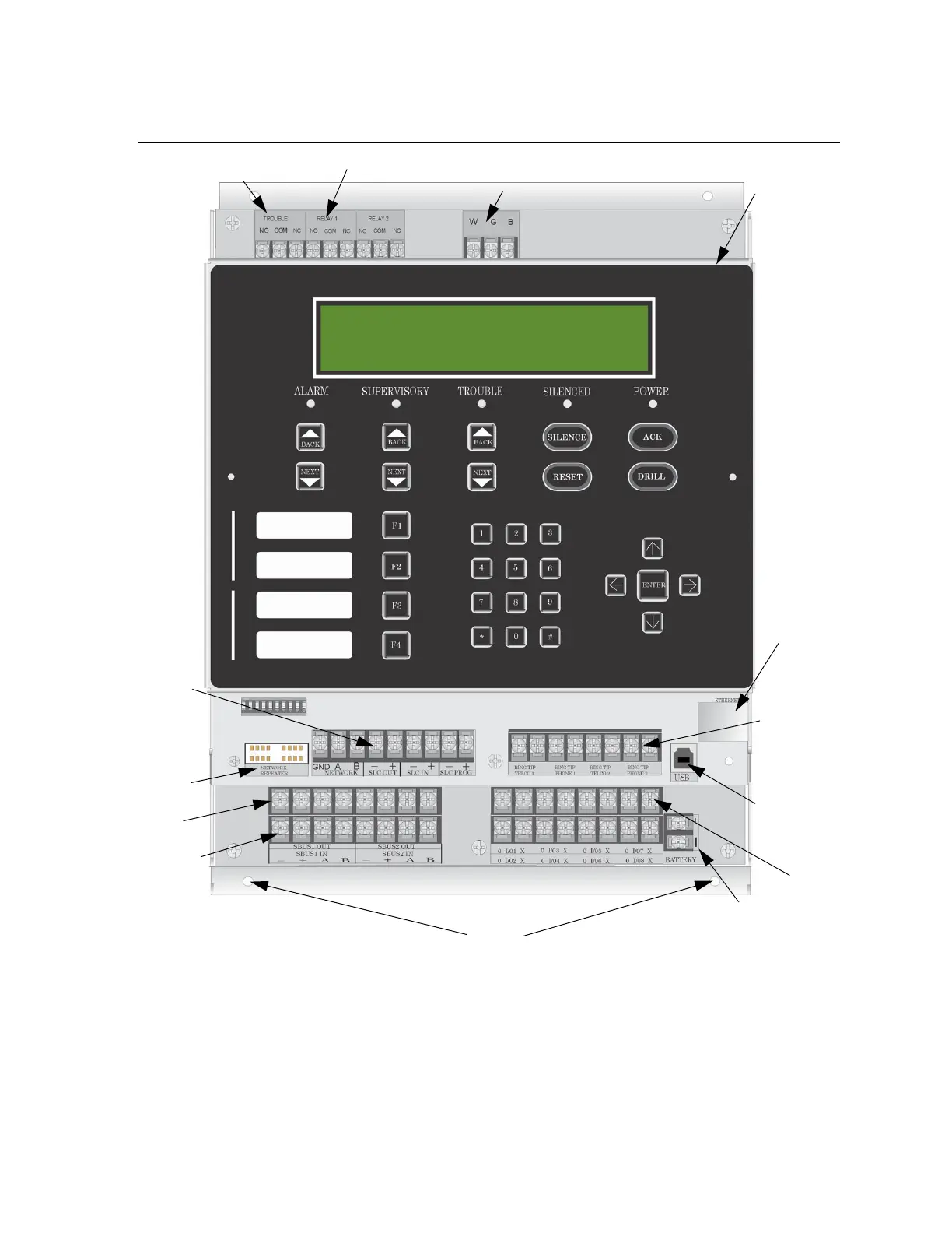
3.5 Board Assembly Diagram
Figure 3-2 Model IFP-2000 Assembly
Figure 3-2 shows the circuit boards, metal housing and annunciator that attach the IFP-2000 assembly to the
cabinet. If you should need to remove the board assembly for repair, remove the four mounting nuts which hold
the assembly in the cabinet. Then lift the entire assembly out of the cabinet. Do not attempt to remove the circuit
boards from the metal bracket.
Chassis
Mounting
Nuts
On-board Annunciator
AC
Trouble
Relay
Phone lines
SLC
In/Out
Battery
Connections
Network
Repeater
USB
Ethernet
Port
Programming
Port
(non-power
limited)
Programmable
Alarm Relay
SBUS In
SBUS Out
Flexput
Circuits
 Loading...

