151430-L8 Control Panel Installation
4-22
4.10 Configuring SBUS Modules
This section describes how to configure any system hardware modules that have been added to the system.
4.10.1 Assigning SBUS Module IDs
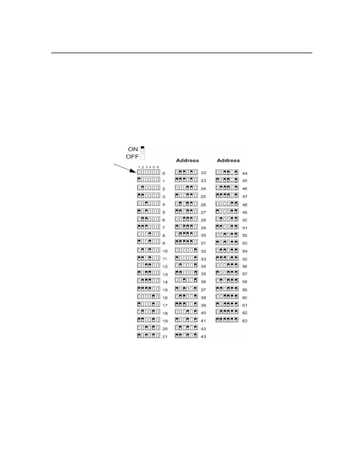
SBUS devices on a panel are addressed from 1 to 63 and are connected to either SBUS 1 or SBUS 2. Although
the addressing scheme allows 63 SBUS devices to be connected to a panel, the actual number is limited by
current draw and SBUS bandwidth usage as discussed below. When installing a hardware module (such as
5815XL, 5824, RA-2000, 5496, RPS-1000, 5865-3 or 5865-4), you must use the DIP switches on the module to
assign an ID# to the module. Address zero is an invalid address and is not allowed.
Figure 4-30 shows all possible DIP switch positions and their correlation to a numerical ID. For example, to
select ID 2, place DIP switch 2 in the up or on position.
Figure 4-30 Possible SBUS module addresses
Refer to Section 9.2 to edit, add, delete, and view module list.
4.10.2 SBUS Bandwidth Considerations
Each SBUS device generates a certain amount of traffic on the SBUS. Generally, the amount of traffic generated
depends on the type of SBUS device. To help you figure out the SBUS bandwidth usage of a given collection of
devices, a tool is available on the Farenhyt website (www.farenhyt.com). The tool will serve as a guide to help
determine how heavily loaded an SBUS is with respect to bandwidth. We recommend you use this tool if you
 Loading...

