Model IFP-2000/ECS Installation Manual 151430-L8
4-11
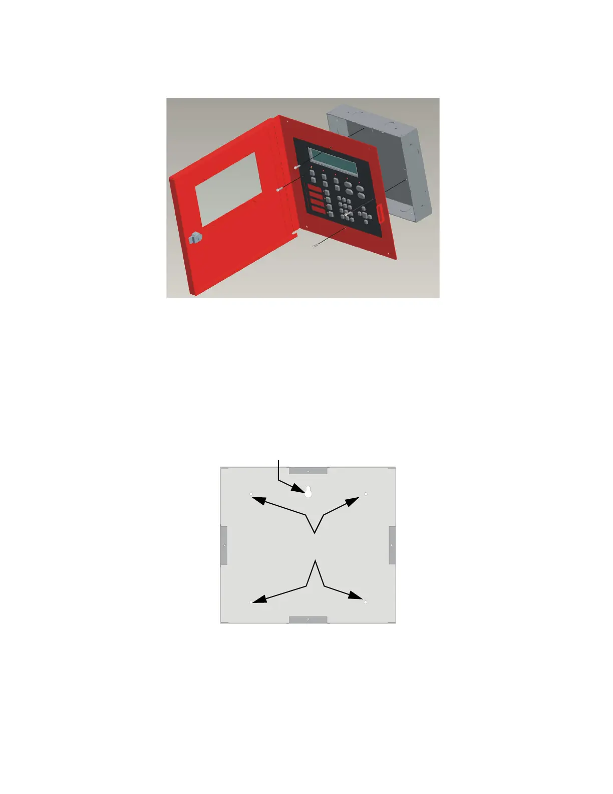
4. Attach the annunciator and door assembly to back box as shown in Figure 4-13 using the supplied screws.
Figure 4-13 Attaching Annunciator / Door Assembly to Backbox
4.5.1.2 Surface Mounting
The Model RA-100TR red trim ring and RA-2000GRAYTR gray trim ring kits are available for use when
surface mounting the RA-2000.
1. Remove the desired knock out. See Figure 4-12.
2. To properly mount the back box, insert a single screw into the key shaped mounting hole. Do not tighten all
the way. See Figure 4-14. Place a level on top of the back box, with the back box level insert the rest of the
mounting screws.
Figure 4-14 Back Box Surface Mount Holes
3. Run wires to the control panel.
Key Shaped
Mounting Hole
Back Box
Mounting Holes
 Loading...

