151430-L8 Networking
5-2
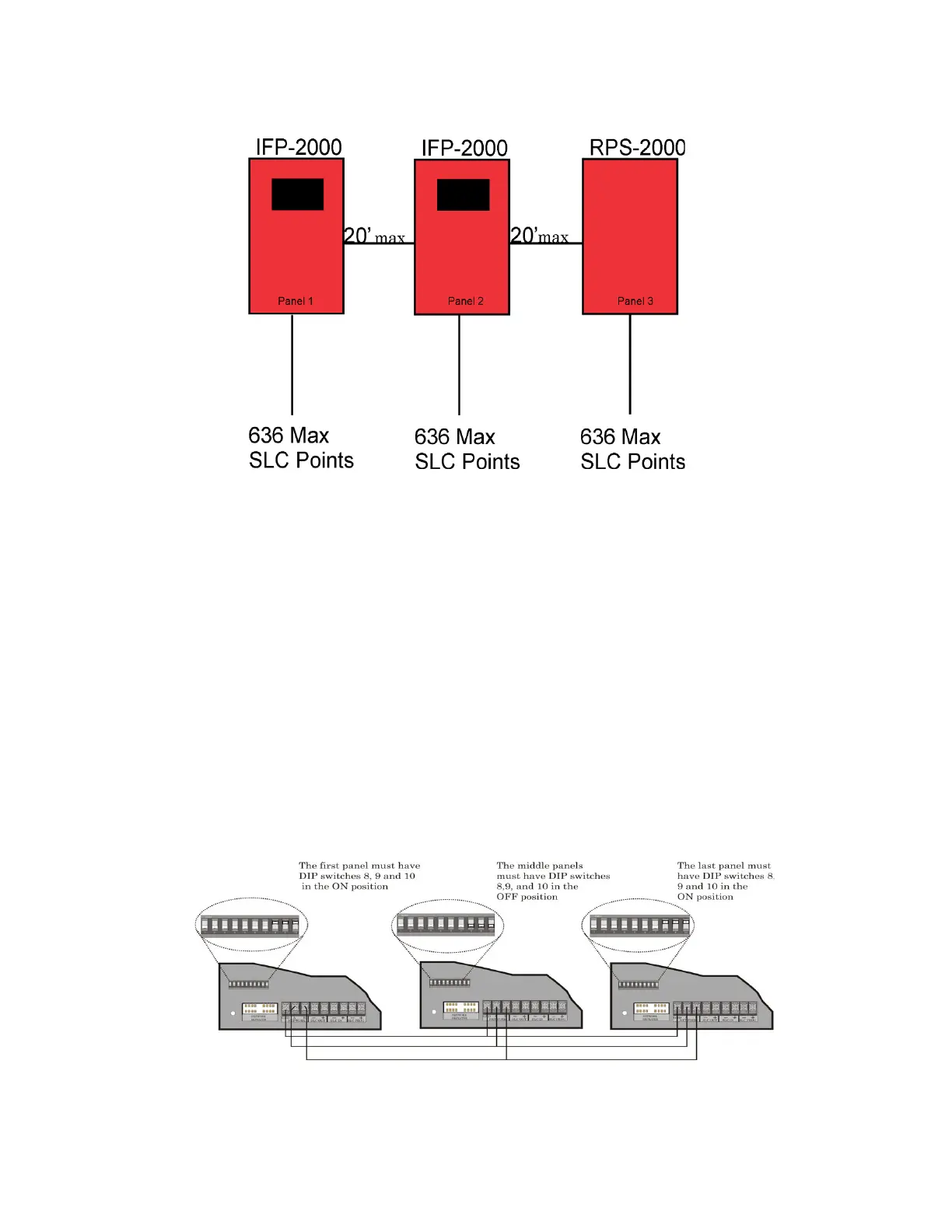
Figure 5-1 Direct Connect Wiring Option
5.3.1 Installing using Direct Connection within a Site:
1. Mount the IFP-2000 and/or RPS-2000 panels within 20 feet of conduit run distance from each other. Place
the conduit for routing the direct connect networking cable between panels in a bus configuration as shown
above in Figure 5-1 on page 2.
2. Make the network wiring connections. The cable used must be shielded twisted pair 18 gauge or larger wire.
See Figure 5-2 on page 2 for the DIP switch termination settings for Direct Connect wire option. Run one of
the twisted pair wires from the NETWORK A terminal on one panel to the NETWORK A terminal on the
next panel. Use the other wire of the twisted pair to connect the NETWORK B terminals together. Run the
network ground connection using the twisted pair shield between the NETWORK GND terminal on both
panels. Repeat this for each additional panel until all A, B and GND terminals are wired together as a BUS.
3. Configure the network terminators. The panels at both ends of the network bus must have DIP switches 8, 9,
and 10 set to the “ON” position. All panels that are not at the BUS ends must have the terminators set to the
OFF position. See Figure 5-2 on page 2.
4. T-Tapping is not allowed; wire must be run in a BUS configuration.
Figure 5-2 DIP Switch Terminations Settings for Direct Connect Wiring Option
 Loading...

