Model IFP-2000/ECS Installation Manual 151430-L8
4-29
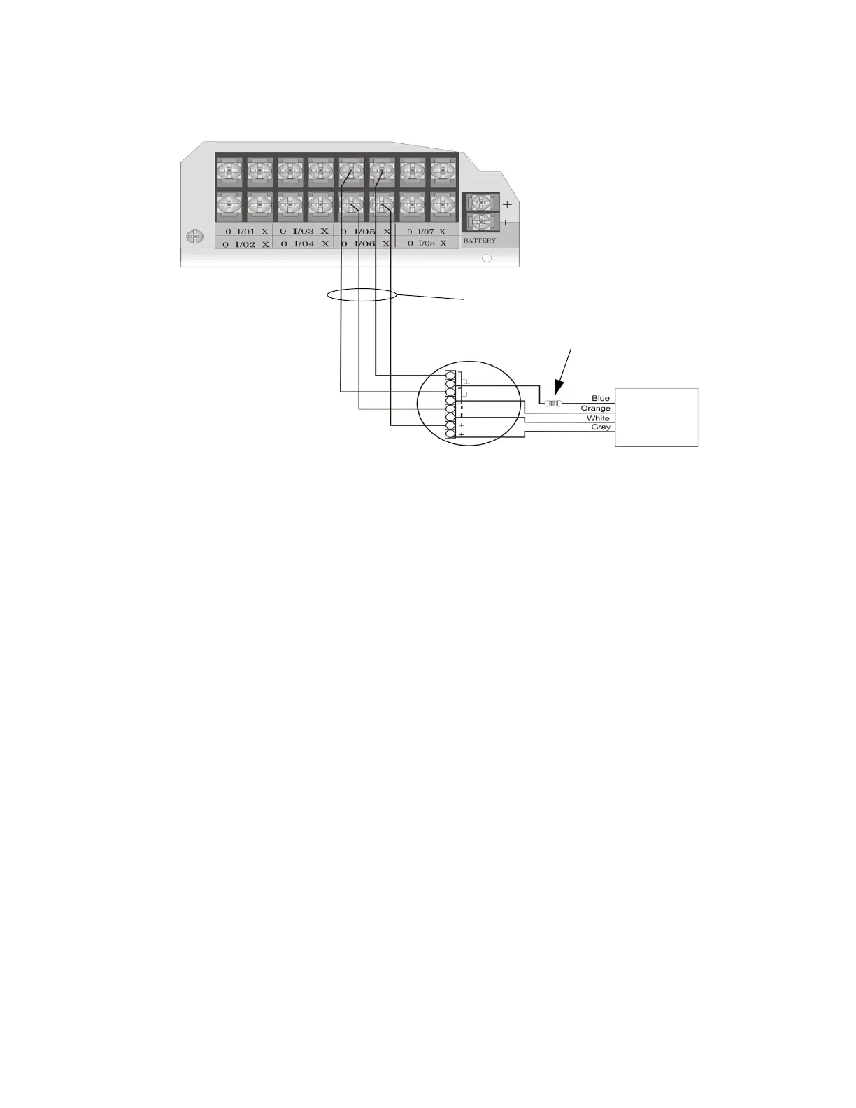
3. Each loop gets smoke power from the even numbered Flexput circuit and the contact input is connected to
the odd numbered Flexput circuit.
Figure 4-38 Class B 4-Wire Smoke Detector Connections
Note: In programming any point that uses multiple Flexput circuits, the lowest Flexput circuit number is used to
refer to the circuit pair. For example, Figure 4-38 uses both Flexput circuit 5 and 6, so in programming it
would be referred to as point 5.
4.12.4.2 Installing 4-Wire Class A Smoke Detectors
Figure 4-39 illustrates how to install 4-wire Class A detectors.
Conventions used for wiring 4-wire Class A loops:
1. Up to two Class A 4-wire loops can be connected to the control panel at once.
Air Products
PAM-2
Model 160150
Supervision
Module
UL Listed
EOL Resistor
ESL 449CT
Note:
Flexput circuit 5 and 6
used as an example.
Any Flexput point pairing
could be used.
supervised
Maximum Impedance
per Circuit is 50
power limited
 Loading...

