151430-L8 Control Panel Installation
4-28
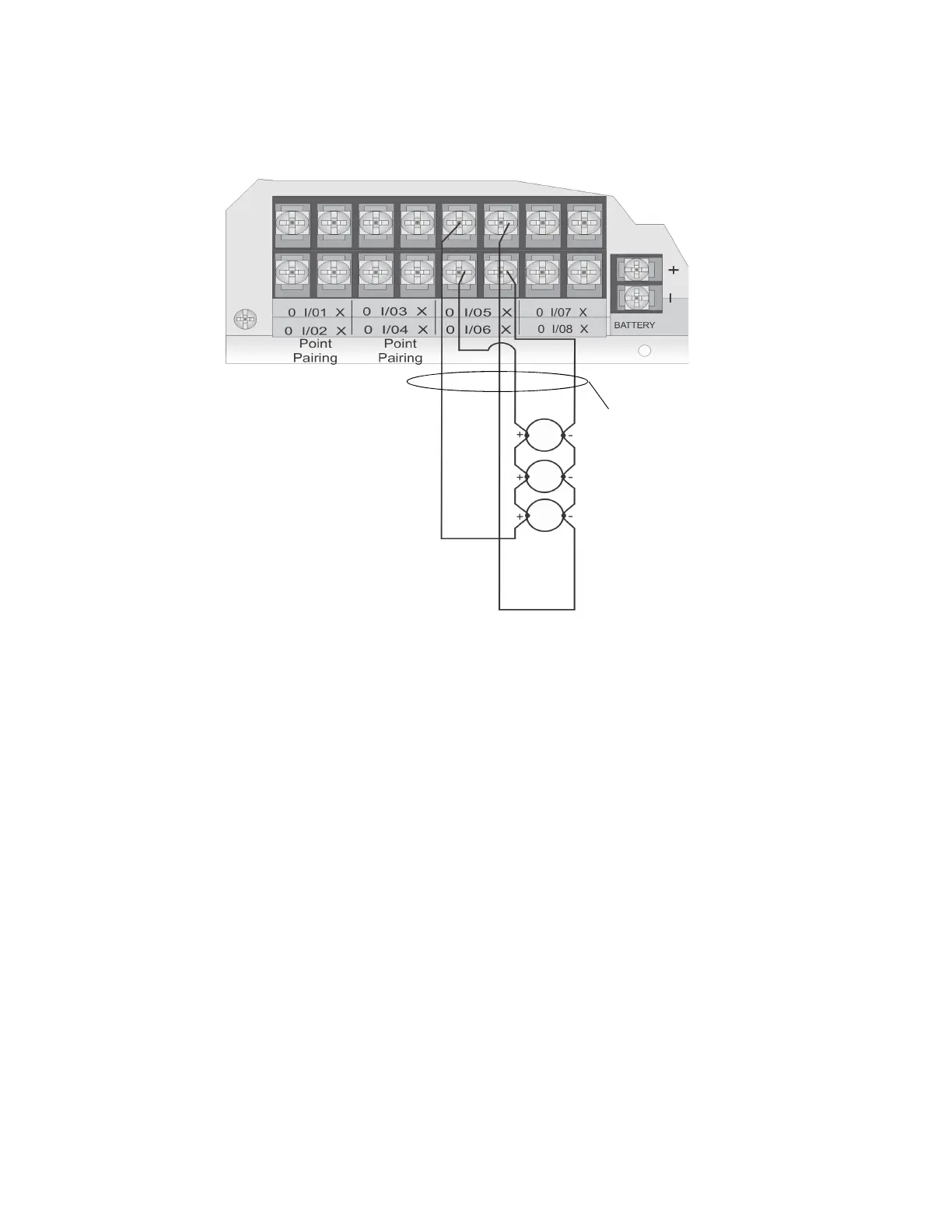
4.12.3.2 Installing 2-Wire Class A Smoke Detectors
To install a Class A two-wire smoke detector, wire as shown in Figure 4-37.
Figure 4-37 Two-Wire Class A Smoke Detector Connections
Note: In programming any point that uses multiple Flexput circuits, the lowest Flexput circuit number is used to
refer to the circuit pair. For example, Figure 4-37 uses both Flexput circuit 5 and 6, so in programming it
would be referred to as point 5.
4.12.4 Installing 4-Wire Smoke Detectors
Any compatible UL listed four-wire smoke detector can be used with the control panel (see Appendix A for list
of compatible smoke detectors). Figure 4-38 and Figure 4-39 illustrate how to connect a UL listed four-wire
detector to the control panel.
4.12.4.1 Installing a Class B 4-Wire Smoke Detectors
Figure 4-38 illustrates how to install a 4-wire Class B smoke detector.
Conventions used for wiring 4-wire Class B loops:
1. Up to four Class B 4-wire smoke detector loops can be connected to the control panel at once.
2. Each Class B loop input is paired with a unique power source as shown in Figure 4-38.
Note:
Flexput circuit 5 and 6
used as an example.
Any Flexput point pairing
could be used.
supervised
power limited
Maximum Impedance per
circuit is 50
Any 2 wire
smoke detector
listed in
Appendix A
 Loading...

