Model IFP-2000/ECS Installation Manual 151430-L8
4-7
Note: The following formulas were used to generate the wire distance chart:
Wiring Distance calculation example:
Suppose a system is configured with the following SBUS modules:
2 - Module RA-2000 Fire Annunciator
1 - RPS-1000 Intelligent Power Expander
1 - 5865 LED Annunciator
1 - 5824 Serial/Parallel Interface Module
The total worst case current is calculated as follows:
Using this value, and referring to the Wiring Distance table, it can be found that the available options are:
370 feet maximum using 22 Gauge wire
938 feet maximum using 18 Gauge wire
1493 feet maximum using 16 Gauge wire
2362 feet maximum using 14 Gauge wire
Maximum Resistance (Ohms) =
6.0 Volts
Total Worst Case Current Draw (amps)
Maximum Wire Length (Feet) =
(6000 feet maximum)
Maximum Resistance (Ohms) * 500
Rpu
where: Rpu = Ohms per 1000 feet for various wire gauges (see table below)
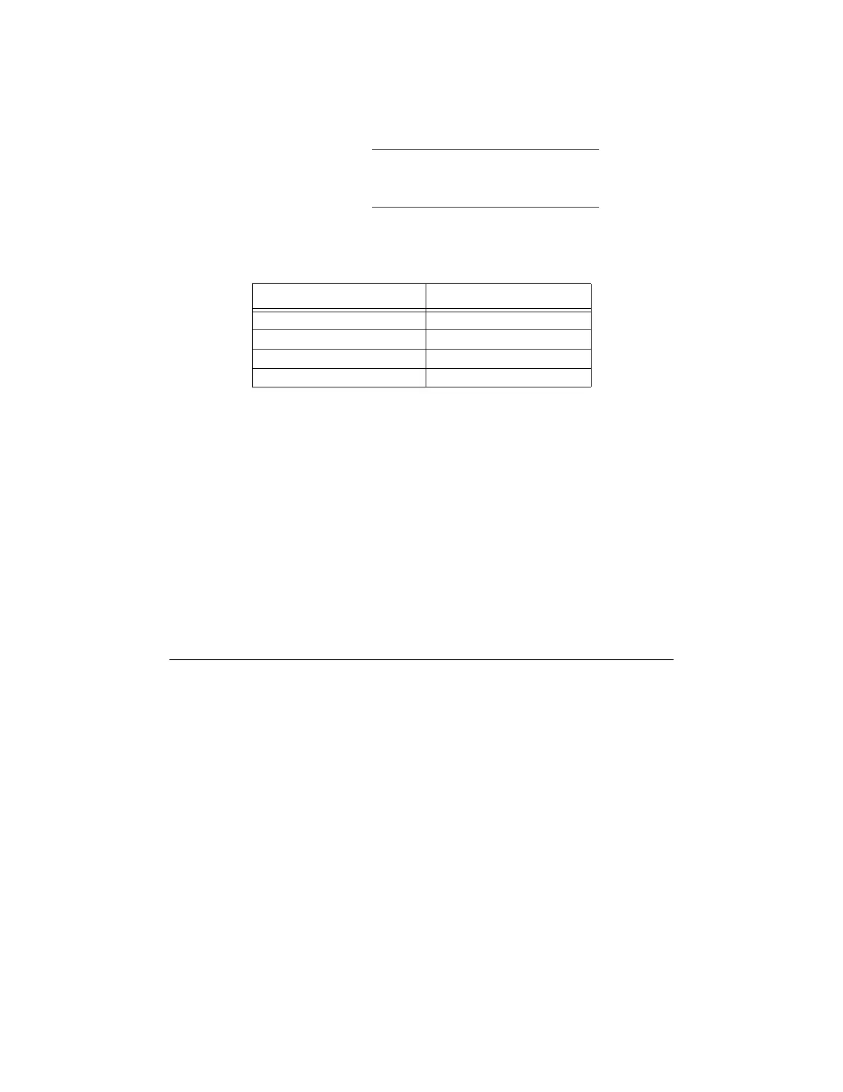
Table 4-2: Typical Wire Resistance Per 1000 ft. Using Copper Wire
Wire Gauge Ohms per 1000 feet (Rpu)
22 16.2
18 6.4
16 4.02
14 2.54
RA-2000 Current Draw = 2 x .120 amps = .240 amps
RPS-1000 Current Draw = 1 x .010 amps = .010 amps
5865 Current Draw = 1 x .200 amps = .200 amps
5824 Current Draw = 1 x .040 amps = .040 amps
Total Worst Case Current Draw = .490 amps
 Loading...

