4. Installation
4.3. Installing Fieldbus RTP TC-FFRU01/TC-FFRP02 or RRTP TC-FFSU01/TC-FFSP02
114 Experion PKS Series A Fieldbus Interface Module User's Guide R400
Honeywell July 2010
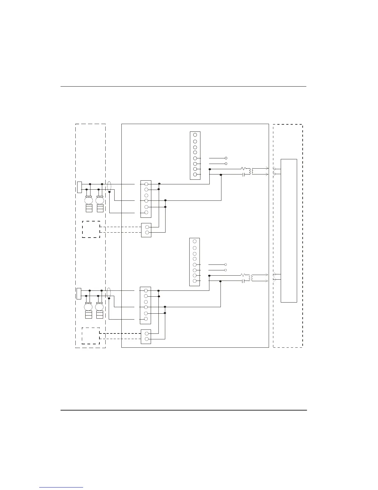
J8
Field Devices
FB+
FB-
J1
14
13
12
11
10
9
8
7
10 Ohm
2.2 uF
T
JP1
Field Wiring
Fieldbus RTP TC-FFRU01
FIM
TC-FFIF01
J3
FB+
FB-
HHC
J5*
1
2
3
4
5
6
J2
1
2
3
4
5
6
14
13
12
11
10
9
8
7
10 Ohm
JP1
Field Devices
FB+
FB+
FB-
FB-
J7
J9*
J1
HHC
1
2
3
4
5
6
SHIELD
14
13
12
11
10
9
8
7
10 Ohm
2.2 uF
T
JP2
Segment 1
Segment 2
IMU
IMU = Integrated Medium Attached Unit (MAU)
HHC = Handheld Communicator
SHIELD
* The mating connector for J5 and J9 is Honeywell part number 51190691-102
or Wiedmuller part number 150186.
Figure 18 Simplified wiring schematic for RTP model TC-FFRU01,
unpowered. Users must provide conditioned 24 Vdc power for the Links -
Not shown
 Loading...