8. Maintenance, Checkout, and Calibration
8.9. Interpreting Component LED Indications
348 Experion PKS Series A Fieldbus Interface Module User's Guide R400
Honeywell July 2010
ATTENTION
You can also create the device type template by selecting device type from
the device list. The OverWrite feature reconfigures the configuration forms to
include the “Enable Block Offnet Diagnostic Alarm” check box.
8.9 Interpreting Component LED Indications
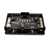
CIOM-A FIM LED indications
As shown in the illustration below, the CIOM-A FIM has one four-character display and
three two-color LEDs on its front panel. From left to right, the LEDs provide Link 1
status, Link 2 status, and module health status, respectively. The following table
summarizes some typical indications for reference.
4-Character
Display
Link 1 Status LED
1
-
10
Link 2 Status LED
Module Health LED
Figure 33 FIM front panel indicators.
Table 1 CIOM-AFIM LED Interpretations
If Module Health
LED is . . .
And, 4-Character
Display shows . . .
Then, FIM is . . .
Flashing Red/Green
TEST
Running its self-test.
Flashing Red/Off
LOAD
In the midst of a firmware load sequence.
Flashing Green/Off
or Solid Green
BOOT
Initiating its startup or boot sequence.
Flashing Green/Off
ALIV
in its ALIVE state and ready for its Personality
Image load.
 Loading...