4. Installation
4.2. Installing CIOM-A Fieldbus Interface Module TC-FFIF01
R400 Experion PKS Series A Fieldbus Interface Module User's Guide 105
July 2010 Honeywell
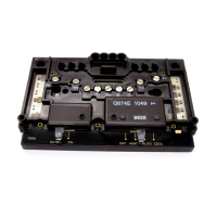
Figure 15 Double-Wide CIOM-A Fieldbus Interface Module TC-FFIF01
Inserting module in chassis
Use t
he following procedure to insert the CIOM-A FIM into the chassis. This procedure
assumes that this is the initial installation of a CIOM-A FIM in an unpowered chassis.
ESD HAZARD
Electrostatic discharge can damage integrated circuits or semiconductors if
you touch backplane connector pins. Follow these guidelines when you
handle a module:
Touch a grounded object to discharge static potential,
Wear an approved wrist-strap grounding device,
Do not touch the backplane connector or connector pins,
Do not touch circuit components inside the module,
If available, use a static safe workstation,
When not in use, keep the module in its static shield box or bag.
Step Action
1
Position the module at the desired chassis slots location. For example, slots 1
and 2.
(Remember that slot numbering is zero-based and the left most slot is
number "0".)
 Loading...