R400 Experion PKS Series A Fieldbus Interface Module User's Guide 511
July 2010 Honeywell
14. Appendix E
14.1 Fieldbus Wiring Considerations
Fieldbus topologies
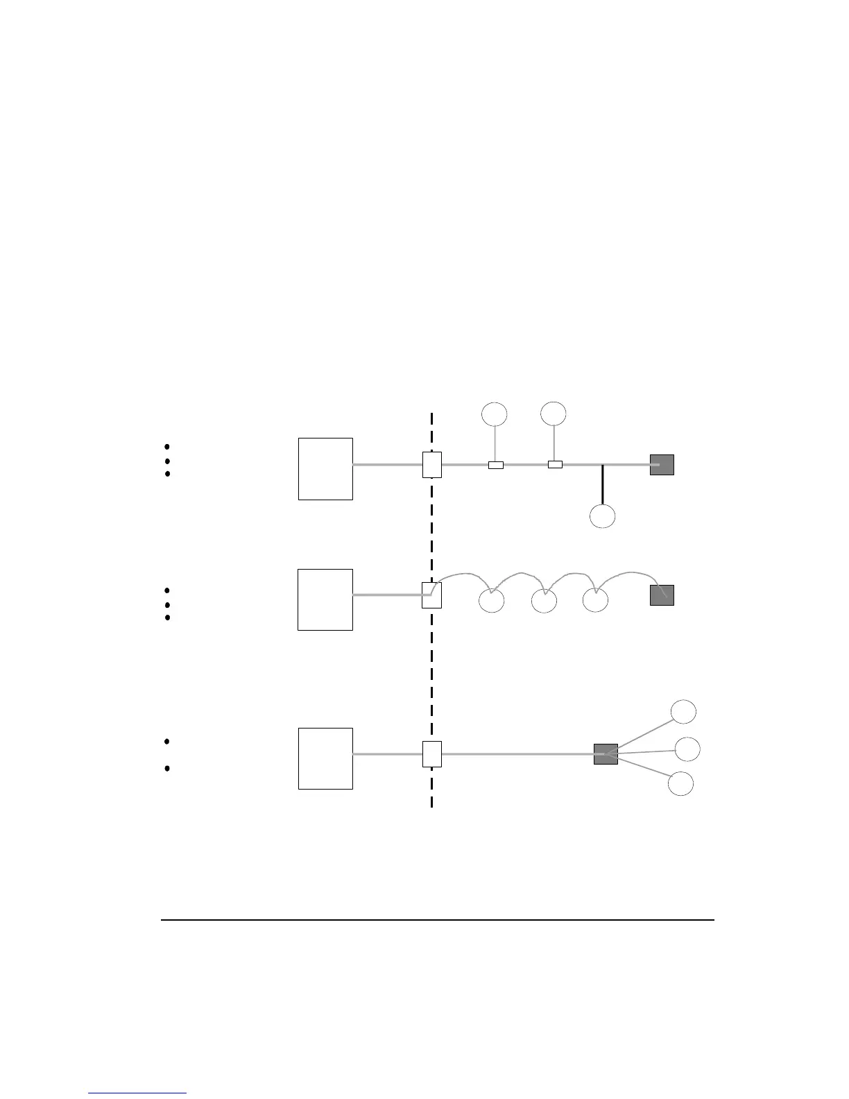
The following figure illustrates the Spur, Daisy Chain, and Tree type wiring topologies
that can be used to connect fieldbus devices to one another and a host.
FD
FD
FD
Host
Terminator
Spurs
(Unterminated)
“Home Run” Cable (Trunk)
I.S.
Barrier
(Optional)
Junction Box
and Terminator
Control Room
FD
FD
FD
Host
Terminator
I.S.
Barrier
(Optional)
Junction Box
and Terminator
FD
FD
FD
Host
Terminator
“Home Run” Cable (Trunk)
I.S.
Barrier
(Optional)
Junction Box
and Terminator
Spur Topology
Reguires layout design
Requires taps
Difficult to change
Daisy Chain Topology
Tree Topology
Requires layout design
Difficult to change
Difficult to maintain
Conforms to present
practices
Wiring savings are
realized only in
“home run” cable
Figure 50 Overview of fieldbus wiring topologies
 Loading...