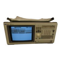
HP 1660 Series TheoryHP 1660 Series Theory
CPU BoardCPU Board
The microprocessor is a Motorola 68EC020 running at 25 MHz. The microprocessor controls
all of t he funct ions of t he logic analyzer including processing and storing dat a, displaying
data, and configuring the acquisition ICs to obtain and store data.
Syst em Memor ySyst em Memor y
The system memory is made up of both read-only memory (ROM) and random access
memory (RAM) . Two types of ROM are used. A single 128Kx8 EPROM is used as a boot
ROM, and eight 128Kx8 Flash ROMS are configured to provide a 256Kx32 Flash ROM space.
Four 1Mx4 DRAMS are configured to provide a 1Mx16 DRAM space.
On power-up, instructions in the boot ROM command the instrument to execute its boot
routine. The boot routine includes power-up operation verification of the instrument
subsystems and entering the operating system. The CPU searches for the operating system
on Flash ROM. Then, if the operating system is in Flash ROM, the instrument will be
initialized with the default configuration and await front panel instructions from you. If the
operat ing syst em is not in Flash ROM, t he CPU accesses t he disk drive t o see if t he operating
system is on the disk.
The DRAM stores the instrument configuration, acquired data to be processed, and any
inverse assembler loaded in the instrument by the user.
CRT Controller and Display RAMCRT Controller and Display RAM
A Brooktree BT476KPJ66 RAMDAC color palette and a National Semiconductor LM1882CM
video frame generator control the CRT. One of the RGB outputs of the color palette provides
the eight-shade grey scale display. The video frame generator provides the horizontal and
vert ical synchronizat ion t iming signals.
The display RAM is made up of two 256Kx4 DRAMS configured as 256Kx8 and stores all of
the pixel information used by the color palette. A serial address counter and an address
multiplexer control the DRAM addressing. At the conclusion of each video frame the vertical
sync signal from the video generat or reset s t he serial address count er and a new frame is
generated.
Disk Drive ControllerDisk Drive Controller
The disk drive controller consists of a single floppy drive controller IC. The floppy drive
controller provides all signals to the disk drive including read and write data, read and write
signals, write gate, and step signal. The floppy drive controller also reads status signals from
t he disk drive, including a track 00 signal, disk ready, and disk change signal.
Keypad and Knob InterfaceKeypad and Knob Interface
The front panel keypad is scanned direct ly from t he microprocessor address bus during t he
video blanking cycle of the CRT. When a front panel key is pressed the associated address
bits are fed to the data bus through the pressed key and read by the microprocessor.
The rotary pulse generator (RPG) knob is part of the HIL circuitry. Pulses and direction of
rotation information are directed to an RPG interface IC and then to the HIL loop. The
microprocessor then reads and interprets t he RPG signals and performs t he desired t asks.
Theory of Operation
The HP 1660 Series Logic Analyzer
8–4

 Loading...