43
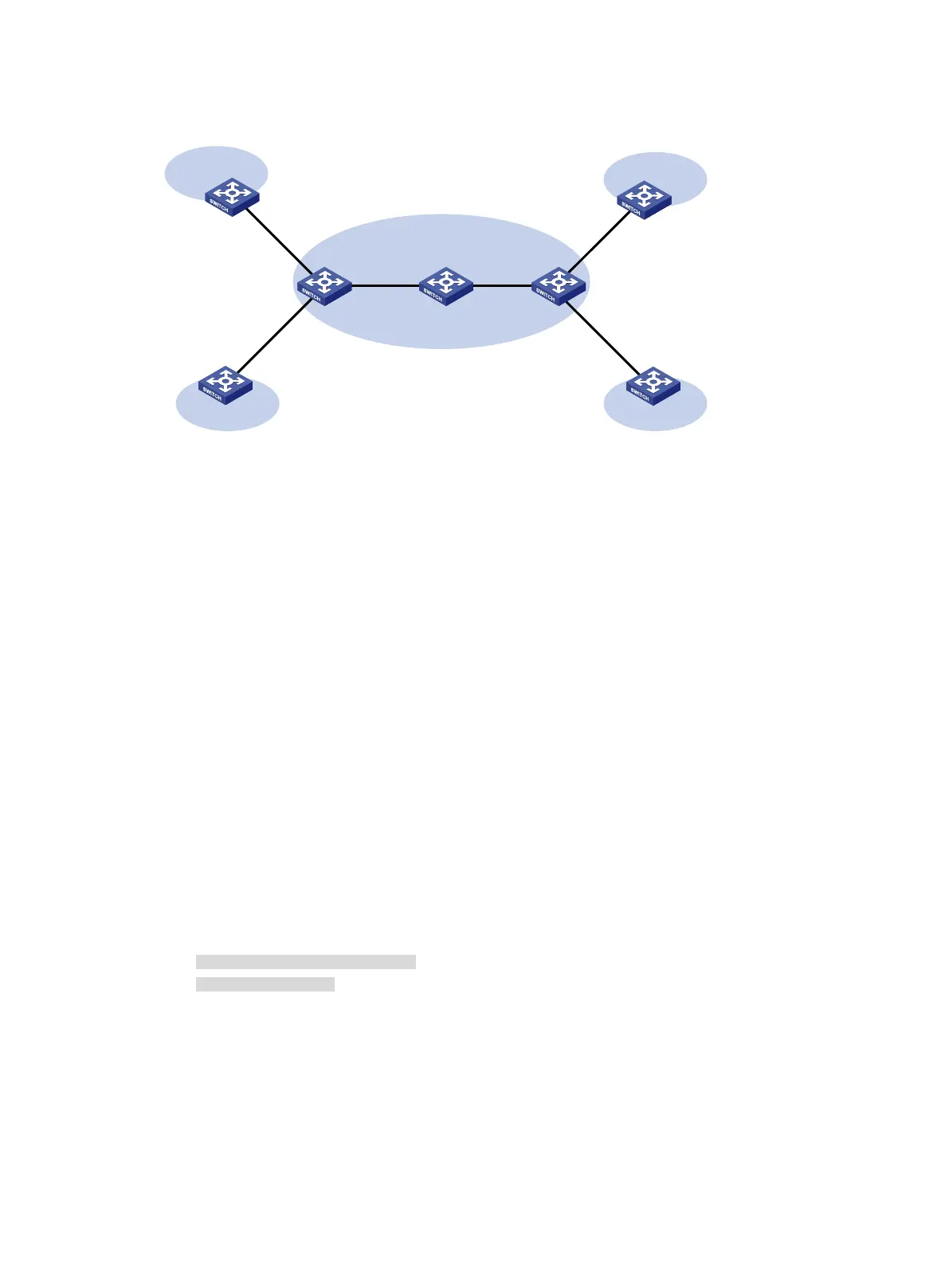
Figure 18 Network diagram
Configuration procedure
Before you perform the following configuration, be sure you have completed MPLS VPN-related
configurations. For information about configuring MPLS VPN, see MPLS Configuration Guide.
1. Set the IP address for each interface, as shown in Figure 18. Make sure CE 1 and PE 1, PE 1
and PE 2, and PE 2 and CE 3 can reach each other. (Details not shown.)
2. Configure CE 1:
# Enable the NTP service.
<CE1> system-view
[CE1] ntp-service enable
# Specify the local clock as the reference source, with the stratum level 2.
[CE1] ntp-service refclock-master 2
3. Configure PE 2:
# Enable the NTP service.
<PE2> system-view
[PE2] ntp-service enable
# Specify CE 1 in VPN 1 as the NTP server of PE 2.
[PE2] ntp-service unicast-server 10.1.1.1 vpn-instance vpn1
4. Verify the configuration:
# Verify that PE 2 has synchronized to CE 1, with the stratum level 3.
[PE2] display ntp-service status
Clock status: synchronized
Clock stratum: 3
System peer: 10.1.1.1
Local mode: client
Reference clock ID: 10.1.1.1
Leap indicator: 00
Clock jitter: 0.005096 s
Stability: 0.000 pps
Clock precision: 2^-10
Root delay: 0.00655 ms
CE 1
NTP server
CE 2 CE 4
CE 3
PE 1
PE 2
NTP client
P
VPN 1
VPN 2
VPN 1
VPN 2
10.1.1.1/24 10.3.1.1/24
10.3.1.2/24
MPLS backbone

 Loading...


