112
Destinations : 13 Routes : 13
Destination/Mask Proto Pre Cost NextHop Interface
0.0.0.0/32 Direct 0 0 127.0.0.1 InLoop0
10.0.0.0/8 O_ASE2 150 2 11.2.1.1 Vlan100
11.2.1.0/24 Direct 0 0 11.2.1.2 Vlan100
11.2.1.0/32 Direct 0 0 11.2.1.2 Vlan100
11.2.1.2/32 Direct 0 0 127.0.0.1 InLoop0
11.2.1.255/32 Direct 0 0 11.2.1.2 Vlan100
127.0.0.0/8 Direct 0 0 127.0.0.1 InLoop0
127.0.0.0/32 Direct 0 0 127.0.0.1 InLoop0
127.0.0.1/32 Direct 0 0 127.0.0.1 InLoop0
127.255.255.255/32 Direct 0 0 127.0.0.1 InLoop0
224.0.0.0/4 Direct 0 0 0.0.0.0 NULL0
224.0.0.0/24 Direct 0 0 0.0.0.0 NULL0
255.255.255.255/32 Direct 0 0 127.0.0.1 InLoop0
The output shows that routes 10.1.1.0/24, 10.2.1.0/24, 10.3.1.0/24 and 10.4.1.0/24 are
summarized into a single route 10.0.0.0/8.
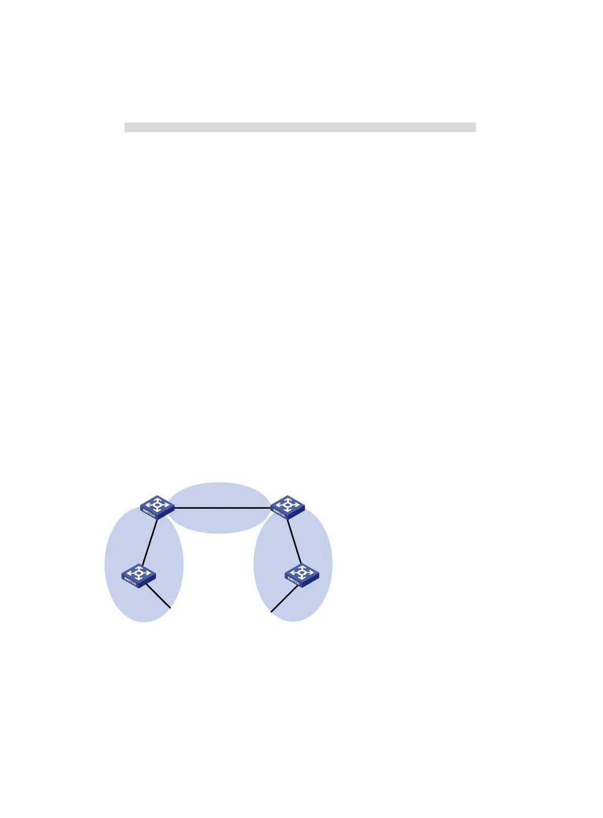
OSPF stub area configuration example
Network requirements
As shown in Figure 27:
• Enable OSPF on all switches, and split the AS into three areas.
• Configure Switch A and Switch B as ABRs to forward routing information between areas.
• Configure Switch D as the ASBR to redistribute static routes.
• Configure Area 1 as a stub area to reduce advertised LSAs without influencing reachability.
Figure 27 Network diagram
Configuration procedure
1. Configure IP addresses for interfaces. (Details not shown.)
2. Enable OSPF (see "Basic OSPF configuration example").
3. Configure route redistribution:
# Configure Switch D to redistribute static routes.
<SwitchD> system-view
[SwitchD] ip route-static 3.1.2.1 24 10.5.1.2
Area 0
Area 1
Stub
Area 2
Switch C
Vlan-int100
10.1.1.2/24
Vlan-int100
10.1.1.1/24
Vlan-int300
10.4.1.1/24
Vlan-int200
10.2.1.2/24
Switch B
Vlan-int200
10.3.1.1/24
Vlan-int200
10.3.1.2/24
Switch A
Vlan-int200
10.2.1.1/24
Vlan-int300
10.5.1.1/24
Switch D
ASBR

 Loading...


