404
Destination: 1::1/128 Protocol : Direct
NextHop : ::1 Preference: 0
Interface : InLoop0 Cost : 0
Destination: 2::/64 Protocol : Direct
NextHop : 2::1 Preference: 0
Interface : Vlan200 Cost : 0
Destination: 2::1/128 Protocol : Direct
NextHop : ::1 Preference: 0
Interface : InLoop0 Cost : 0
Destination: 4::/64 Protocol : RIPng
NextHop : FE80::200:BFF:FE01:1C02 Preference: 100
Interface : Vlan100 Cost : 1
Destination: FE80::/10 Protocol : Direct
NextHop : :: Preference: 0
Interface : NULL0 Cost : 0
Destination: FF00::/8 Protocol : Direct
NextHop : :: Preference: 0
Interface : NULL0 Cost : 0
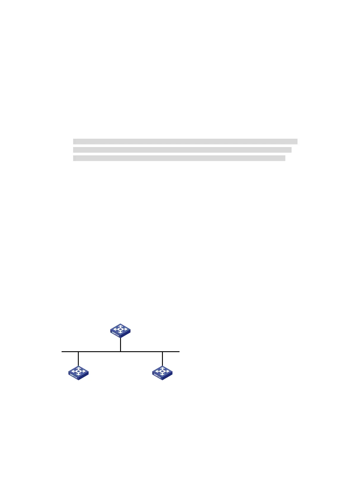
RIPng GR configuration example
Network requirements
As shown in Figure 95, Switch A, Switch B, and Switch C learn IPv6 routing information through
RIPng.
Configure Switch A as the GR restarter. Configure Switch B and Switch C as the GR helpers to
synchronize their routing tables with Switch A by using GR.
Figure 95 Network diagram
Configuration procedure
1. Configure IPv6 addresses for interfaces. (Details not shown.)
2. Configure RIPng on the switches to ensure the following: (Details not shown.)
Switch A, Switch B, and Switch C can communicate with each other at Layer 3.
Vlan-int100
2000::1/24
Vlan-int100
2000::3/24
Vlan-int100
2000::2/24
GR helper GR helper
GR restarter
Switch A
Switch CSwitch B
Router ID: 1.1.1.1
Router ID: 2.2.2.2
Router ID: 3.3.3.3

 Loading...


