44
RIP configuration examples
Configuring basic RIP
Network requirements
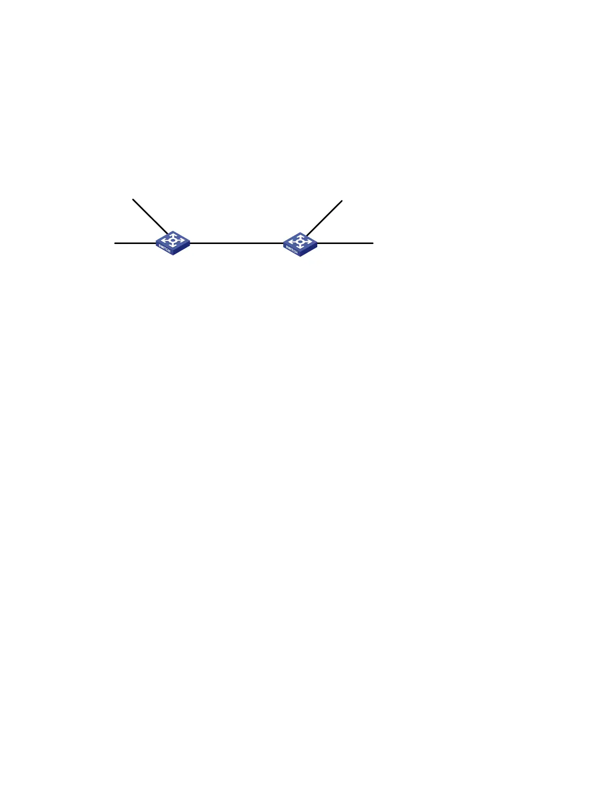
As shown in Figure 7, enable RIPv2 on all interfaces on Switch A and Switch B. Configure Switch B
to not advertise route 10.2.1.0/24 to Switch A, and to accept only route 2.1.1.0/24 from Switch A.
Figure 7 Network diagram
Configuration procedure
1. Configure IP addresses for interfaces. (Details not shown.)
2. Configure basic RIP by using either of the following methods:
(Method 1) # Enable RIP on the specified networks on Switch A.
<SwitchA> system-view
[SwitchA] rip
[SwitchA-rip-1] network 1.0.0.0
[SwitchA-rip-1] network 2.0.0.0
[SwitchA-rip-1] network 3.0.0.0
[SwitchA-rip-1] quit
(Method 2) # Enable RIP on the specified interfaces on Switch B.
<SwitchB> system-view
[SwitchB] rip
[SwitchB-rip-1] quit
[SwitchB] interface vlan-interface 100
[SwitchB-Vlan-interface100] rip 1 enable
[SwitchB-Vlan-interface100] quit
[SwitchB] interface vlan-interface 101
[SwitchB-Vlan-interface101] rip 1 enable
[SwitchB-Vlan-interface101] quit
[SwitchB] interface vlan-interface 102
[SwitchB-Vlan-interface102] rip 1 enable
[SwitchB-Vlan-interface102] quit
# Display the RIP routing table of Switch A.
[SwitchA] display rip 1 route
Route Flags: R - RIP, T - TRIP
P - Permanent, A - Aging, S - Suppressed, G - Garbage-collect
D - Direct, O - Optimal, F - Flush to RIB
----------------------------------------------------------------------------
Peer 1.1.1.2 on Vlan-interface100
Destination/Mask Nexthop Cost Tag Flags Sec
10.0.0.0/8 1.1.1.2 1 0 RAOF 11
Vlan-int102
2.1.1.1/24
Vlan-int100
1.1.1.2/24
Vlan-int102
10.1.1.2/24
Vlan-int100
1.1.1.1/24
Vlan-int101
10.2.1.1/24
Vlan-int101
3.1.1.1/24
Switch A Switch B

 Loading...


