127
14.14.14.0/24 1 Transit 14.14.14.1 4.4.4.1 0.0.0.0
22.22.22.22/32 2 Stub 14.14.14.2 2.2.2.1 0.0.0.0
12.12.12.0/24 2 Transit 14.14.14.2 2.2.2.1 0.0.0.0
Total nets: 4
Intra area: 4 Inter area: 0 ASE: 0 NSSA: 0
The output shows the following when an active/standby switchover occurs on Switch S:
• The neighbor relationships and routing information on Switch A and Switch B have not
changed.
• The traffic from Switch A to Switch B has not been impacted.
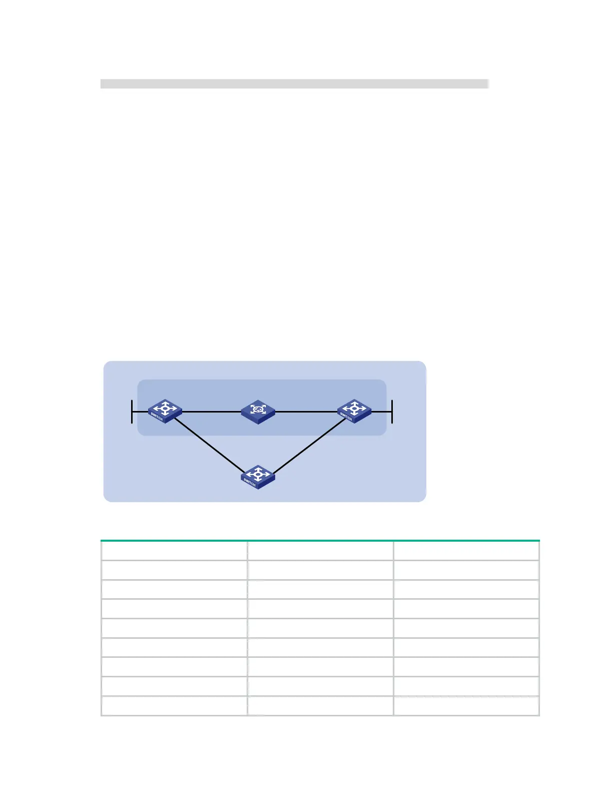
BFD for OSPF configuration example
Network requirements
As shown in Figure 33, run OSPF on Switch A, Switch B, and Switch C so that they are reachable to
each other at the network layer.
• When the link over which Switch A and Switch B communicate through a Layer 2 switch fails,
BFD can quickly detect the failure and notify OSPF of the failure.
• Switch A and Switch B then communicate through Switch C.
Figure 33 Network diagram
Table 9 Interface and IP address assignment
Switch A Vlan-int10 192.168.0.102/24
Switch A Vlan-int11 10.1.1.102/24
Switch A Loop0 121.1.1.1/32
Switch B Vlan-int10 192.168.0.100/24
Switch B Vlan-int13 13.1.1.1/24
Switch B Loop0 120.1.1.1/32
Switch C Vlan-int11 10.1.1.100/24
Switch C Vlan-int13 13.1.1.2/24
Switch A Switch B
Vlan-int10
Vlan-int10
BFD
L2 Switch
Area 0
Switch C
Vlan-int11
Vlan-int11
Vlan-int13
Vlan-int13
Loop0
Loop0

 Loading...


