313
BGP Routing table Status : <Inactive>
Summary count : 0
The output shows that Switch D has only one route 192.168.64.0/18 to AS 65106.
# Verify that Switch D can ping the hosts on networks 192.168.64.0/24, 192.168.74.0/24, and
192.168.99.0/24. (Details not shown.)
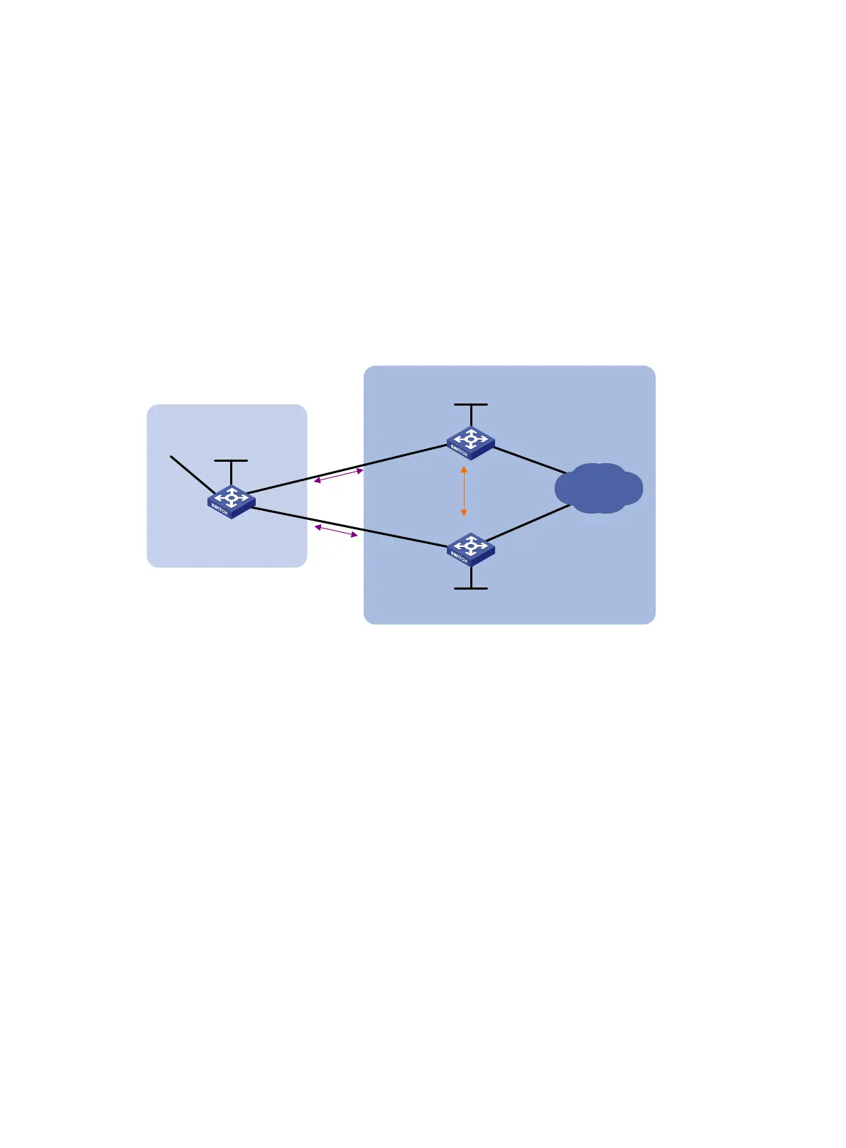
BGP load balancing configuration example
Network requirements
As shown in Figure 69, run EBGP between Switch A and Switch B, and between Switch A and Switch
C. Run IBGP between Switch B and Switch C. Configure load balancing over the two EBGP links on
Switch A.
Figure 69 Network diagram
Configuration considerations
On Switch A:
• Establish EBGP connections with Switch B and Switch C.
• Configure BGP to advertise network 8.1.1.0/24 to Switch B and Switch C, so that Switch B and
Switch C can access the internal network connected to Switch A.
On Switch B:
• Establish an EBGP connection with Switch A and an IBGP connection with Switch C.
• Configure BGP to advertise network 9.1.1.0/24 to Switch A, so that Switch A can access the
intranet through Switch B.
• Configure a static route to interface loopback 0 on Switch C (or use a routing protocol like
OSPF) to establish the IBGP connection.
On Switch C:
• Establish an EBGP connection with Switch A and an IBGP connection with Switch B.
• Configure BGP to advertise network 9.1.1.0/24 to Switch A, so that Switch A can access the
intranet through Switch C.
• Configure a static route to interface loopback 0 on Switch B (or use another protocol like OSPF)
to establish the IBGP connection.
Configure load balancing on Switch A.
Vlan-int200
3.1.1.2/24
Switch A
AS 65008
Vlan-int400
9.1.1.2/24
Vlan-int300
3.1.2.1/24
Vlan-int200
3.1.1.1/24
Switch B
Switch C
AS 65009
Vlan-int300
3.1.2.2/24
Vlan-int400
9.1.1.1/24
EBGP
EBGP
IBGP
Loop0
1.1.1.1/32
Loop0
2.2.2.2/32
Loop0
3.3.3.3/32
Intranet

 Loading...


