319
Total number of routes: 0
The output shows that BGP has not learned any route.
BGP route reflector configuration example
Network requirements
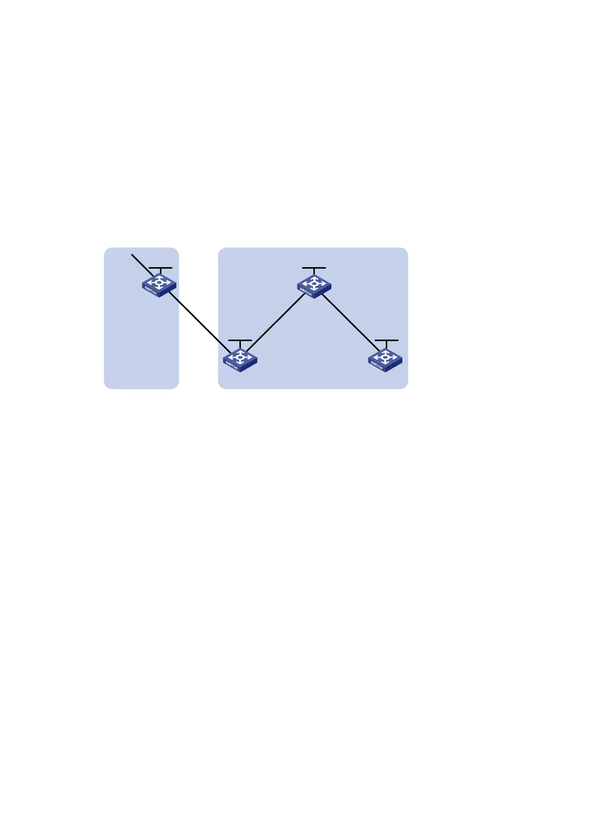
As shown in Figure 71, all switches run BGP. Run EBGP between Switch A and Switch B, and run
IBGP between Switch C and Switch B, and between Switch C and Switch D.
Configure Switch C as a route reflector with clients Switch B and Switch D to allow Switch D to learn
route 20.0.0.0/8 from Switch C.
Figure 71 Network diagram
Configuration procedure
1. Configure IP addresses for interfaces and configure OSPF in AS 200. (Details not shown.)
2. Configure BGP connections:
# Configure Switch A.
<SwitchA> system-view
[SwitchA] bgp 100
[SwitchA-bgp-default] router-id 1.1.1.1
[SwitchA-bgp-default] peer 192.1.1.2 as-number 200
[SwitchA-bgp-default] address-family ipv4 unicast
[SwitchA-bgp-default-ipv4] peer 192.1.1.2 enable
# Inject network 20.0.0.0/8 to the BGP routing table.
[SwitchA-bgp-default-ipv4] network 20.0.0.0
[SwitchA-bgp-default-ipv4] quit
[SwitchA-bgp-default] quit
# Configure Switch B.
<SwitchB> system-view
[SwitchB] bgp 200
[SwitchB-bgp-default] router-id 2.2.2.2
[SwitchB-bgp-default] peer 192.1.1.1 as-number 100
[SwitchB-bgp-default] peer 193.1.1.1 as-number 200
[SwitchB-bgp-default] address-family ipv4 unicast
[SwitchB-bgp-default-ipv4] peer 192.1.1.1 enable
[SwitchB-bgp-default-ipv4] peer 193.1.1.1 enable
Vlan-int200
192.1.1.1/24
Switch A
AS 100
Vlan-int200
192.1.1.2/24
Vlan-int100
20.1.1.1/8
Vlan-int300
193.1.1.2/24
Vlan-int400
194.1.1.2/24
Vlan-int400
194.1.1.1/24
Vlan-int300
193.1.1.1/24
Switch C
Switch B
Switch D
AS 200
Route reflector
Loop0
1.1.1.1/32
Loop0
3.3.3.3/32
Loop0
2.2.2.2/32
Loop0
4.4.4.4/32

 Loading...


