353
* > Network : 10::2 PrefixLen : 128
NextHop : ::1 LocPrf :
PrefVal : 32768 OutLabel : NULL
MED : 0
Path/Ogn: ?
* >i Network : 20:: PrefixLen : 64
NextHop : ::FFFF:3.3.3.3 LocPrf : 100
PrefVal : 0 OutLabel : 1278
MED : 0
Path/Ogn: ?
# Verify that CE 1 can ping the IPv6 address 4::4 (loopback interface address) of CE 2. (Details not
shown.)
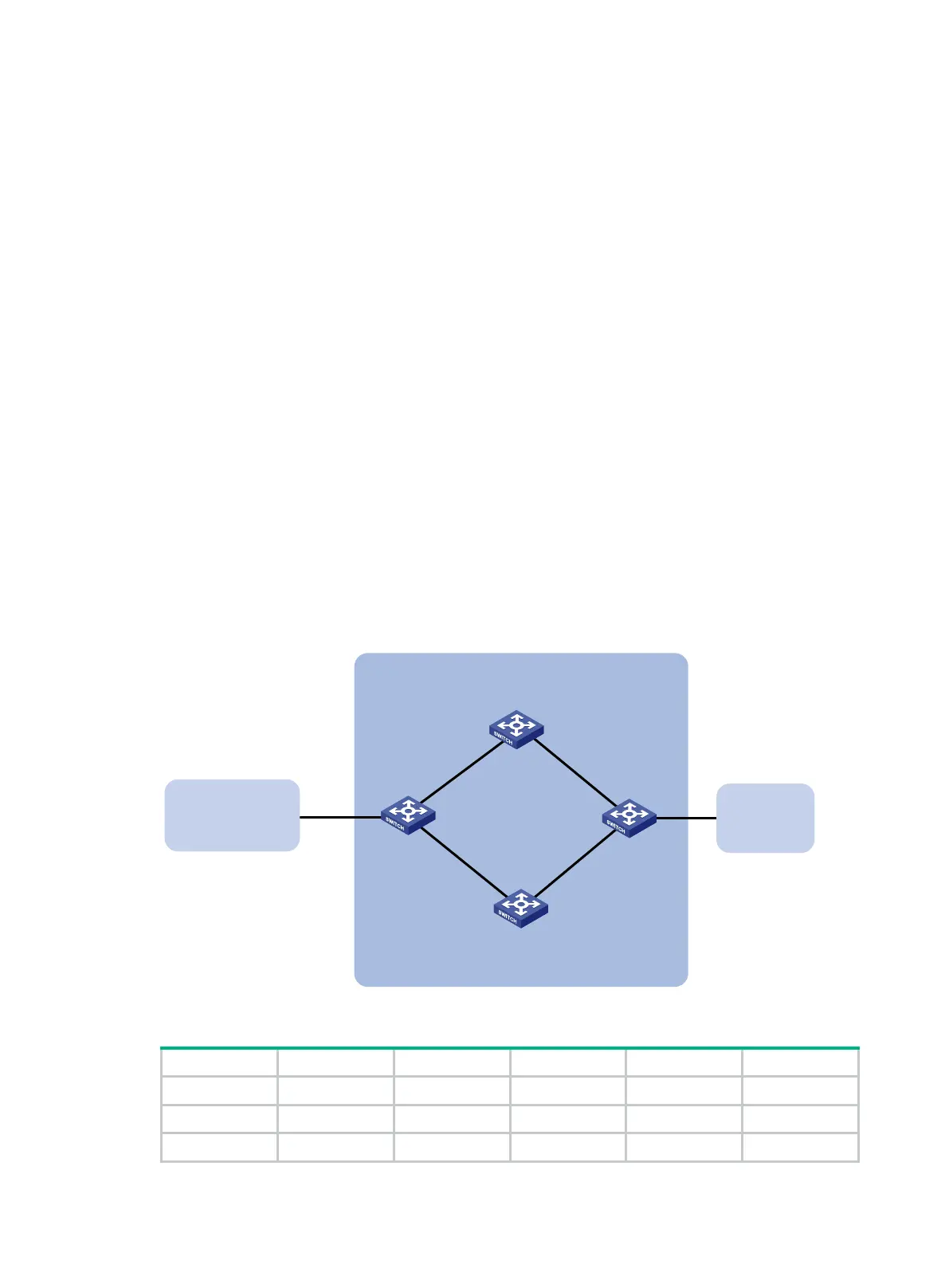
BFD for IPv6 BGP configuration example
Network requirements
As shown in Figure 83, configure OSPFv3 as the IGP in AS 200.
• Establish two IBGP connections between Switch A and Switch C. When both paths operate
correctly, Switch C uses the path Switch A<—>Switch B<—>Switch C to exchange packets
with network 1200::0/64.
• Configure BFD over the path. When the path fails, BFD can quickly detect the failure and notify
it to IPv6 BGP. Then, the path Switch A<—>Switch D<—>Switch C takes effect immediately.
Figure 83 Network diagram
Table 21 Interface and IP address assignment
Switch A Vlan-int100 3000::1/64 Switch C Vlan-int101 3001::3/64
Vlan-int200 2000::1/64 Vlan-int201 2001::3/64
Switch B Vlan-int100 3000::2/64 Switch D Vlan-int200 2000::2/64
Switch A Switch C
AS 200
Switch D
Vlan-int200
Vlan-int201
Switch B
AS 300
Vlan-int101Vlan-int100
Vlan-int100
Vlan-int101
Vlan-int200
Vlan-int201
AS 100
1200::0/64

 Loading...


