307
Network NextHop MED LocPrf PrefVal Path/Ogn
* >i 2.2.2.2/32 2.2.2.2 0 100 0 ?
* >i 3.1.1.0/24 2.2.2.2 0 100 0 ?
* >i 8.1.1.0/24 3.1.1.2 0 100 0 65008i
* >i 9.1.1.0/24 2.2.2.2 0 100 0 ?
The output shows that the route 8.1.1.0 becomes valid with the next hop as Switch A.
Verifying the configuration
# Verify that Switch C can ping 8.1.1.1.
[SwitchC] ping 8.1.1.1
Ping 8.1.1.1 (8.1.1.1): 56 data bytes, press CTRL_C to break
56 bytes from 8.1.1.1: icmp_seq=0 ttl=254 time=10.000 ms
56 bytes from 8.1.1.1: icmp_seq=1 ttl=254 time=4.000 ms
56 bytes from 8.1.1.1: icmp_seq=2 ttl=254 time=4.000 ms
56 bytes from 8.1.1.1: icmp_seq=3 ttl=254 time=3.000 ms
56 bytes from 8.1.1.1: icmp_seq=4 ttl=254 time=3.000 ms
--- Ping statistics for 8.1.1.1 ---
5 packet(s) transmitted, 5 packet(s) received, 0.0% packet loss
round-trip min/avg/max/std-dev = 3.000/4.800/10.000/2.638 ms
BGP and IGP route redistribution configuration example
Network requirements
As shown in Figure 67, all devices of company A belong to AS 65008, and all devices of company B
belong to AS 65009.
Configure BGP and IGP route redistribution to allow Switch A to access network 9.1.2.0/24 in AS
65009, and Switch C to access network 8.1.1.0/24 in AS 65008.
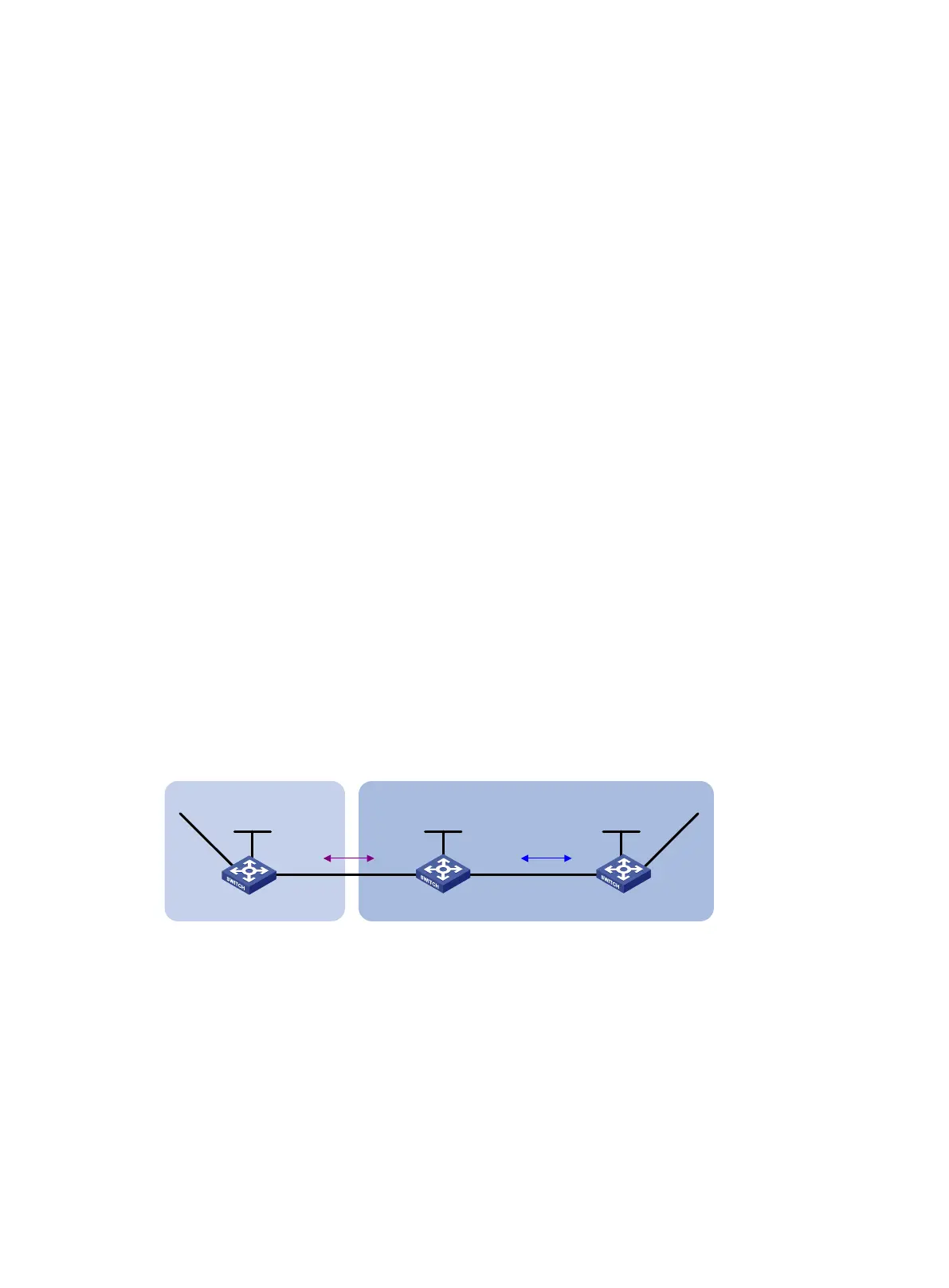
Figure 67 Network diagram
Configuration considerations
Configure BGP to redistribute routes from OSPF on Switch B, so Switch A can obtain the route to
9.1.2.0/24. Configure OSPF to redistribute routes from BGP on Switch B, so Switch C can obtain the
route to 8.1.1.0/24.
Configuration procedure
1. Configure IP addresses for interfaces. (Details not shown.)
2. Configure OSPF:
Enable OSPF in AS 65009, so Switch B can obtain the route to 9.1.2.0/24.
# Configure Switch B.
Switch A
AS 65008
Vlan-int200
3.1.1.1/24
Switch C
Switch B
AS 65009
Vlan-int100
8.1.1.1/24
Vlan-int200
3.1.1.2/24
Vlan-int300
9.1.1.1/24
Vlan-int300
9.1.1.2/24
Loop0
1.1.1.1/32
Loop0
2.2.2.2/32
Loop0
3.3.3.3/32
EBGP
OSPF
Vlan-int400
9.1.2.1/24

 Loading...


