481
Destination: 2001:4::/64 Protocol : IS_L1
NextHop : FE80::BAAF:67FF:FE27:DCD0 Preference: 15
Interface : Vlan11 Cost : 20
The output shows that Switch A and Switch B communicate through VLAN-interface 11.
IPv6 IS-IS FRR configuration example
Network requirements
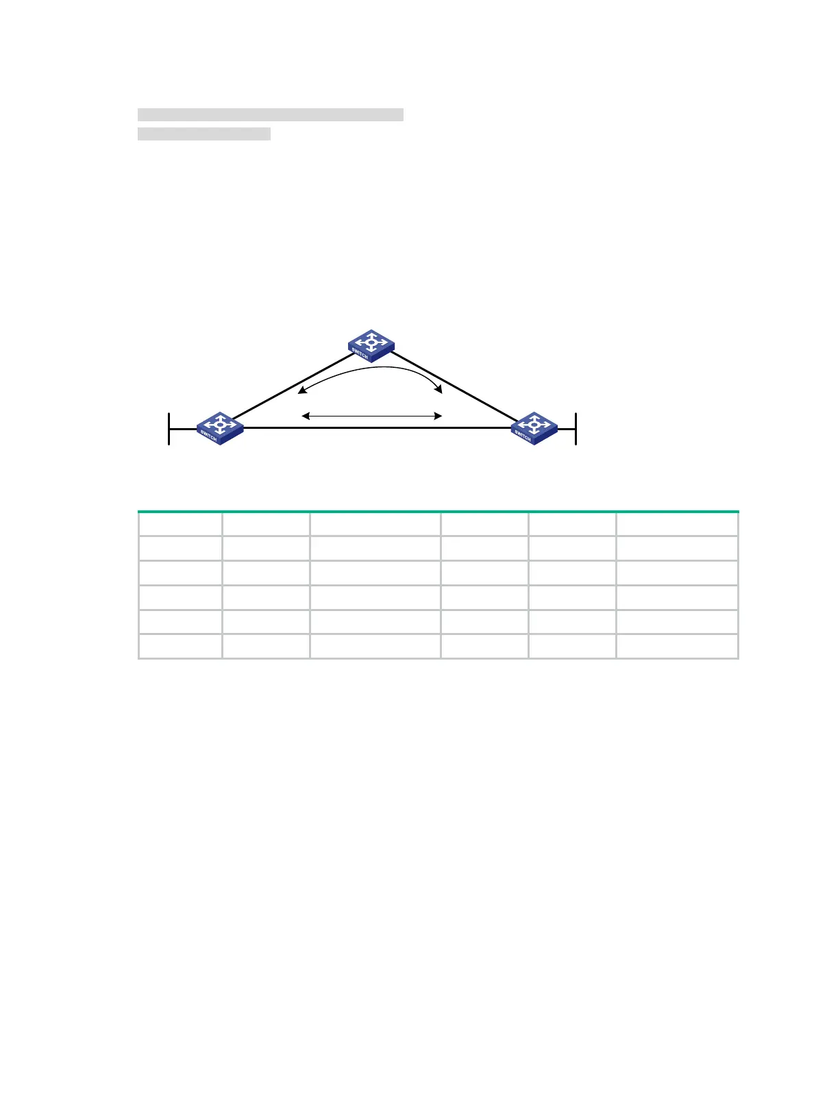
As shown in Figure 114, Switch A, Switch B, and Switch C belong to the same IS-IS routing domain.
Configure IPv6 IS-IS FRR so that when the Link A fails, traffic can be switched to Link B immediately.
Figure 114 Network diagram
Table 28 Interface and IP address assignment
Switch A Vlan-int100 1::1/64 Switch B Vlan-int101 3::1/64
Vlan-int200 2::1/64 Vlan-int200 2::2/64
Loop0 10::1/128 Loop0 20::1/128
Switch C Vlan-int100 1::2/64
Vlan-int101 3::2/64
Configuration procedure
1. Configure IPv6 addresses for interfaces on the switches and enable IPv6 IS-IS. (Details not
shown.)
2. Configure IPv6 IS-IS on the switches to make sure Switch A, Switch B, and Switch C can
communicate with each other at Layer 3. (Details not shown.)
3. Configure IPv6 IS-IS FRR:
Enable IPv6 IS-IS FRR to calculate a backup next hop through LFA calculation, or designate a
backup next hop by using a referenced routing policy.
(Method 1.) Enable IPv6 IS-IS FRR to calculate a backup next hop through LFA calculation:
# Configure Switch A.
<SwitchA> system-view
[SwitchA] isis 1
[SwitchA-isis-1] address-family ipv6
[SwitchA-isis-1-ipv6] fast-reroute lfa
# Configure Switch B.
<SwitchB> system-view
[SwitchB] isis 1
Switch A Switch B
Switch C
Loop0
Vlan-int100
Vlan-int200
Vlan-int200
Vlan-int100
Vlan-int101
Vlan-int101
Loop0
Link A
Link B

 Loading...


