316
BGP community configuration example
Network requirements
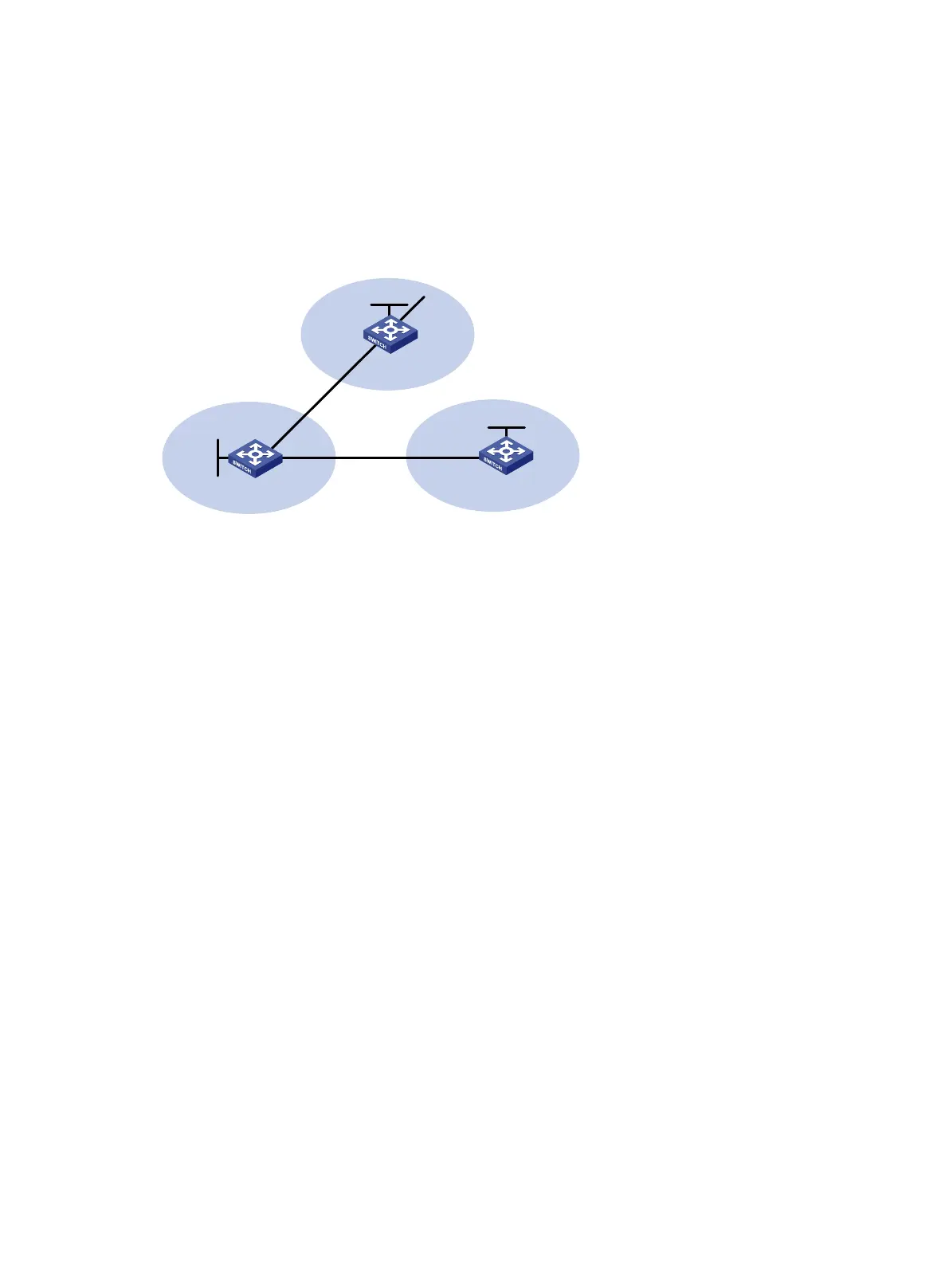
As shown in Figure 70, Switch B establishes EBGP connections with Switch A and Switch C.
Configure NO_EXPORT community attribute on Switch A to make routes from AS 10 not advertised
by AS 20 to any other AS.
Figure 70 Network diagram
Configuration procedure
1. Configure IP addresses for interfaces. (Details not shown.)
2. Configure EBGP connections:
# Configure Switch A.
<SwitchA> system-view
[SwitchA] bgp 10
[SwitchA-bgp-default] router-id 1.1.1.1
[SwitchA-bgp-default] peer 200.1.2.2 as-number 20
[SwitchA-bgp-default] address-family ipv4 unicast
[SwitchA-bgp-default-ipv4] peer 200.1.2.2 enable
[SwitchA-bgp-default-ipv4] network 9.1.1.0 255.255.255.0
[SwitchA-bgp-default] quit
# Configure Switch B.
<SwitchB> system-view
[SwitchB] bgp 20
[SwitchB-bgp-default] router-id 2.2.2.2
[SwitchB-bgp-default] peer 200.1.2.1 as-number 10
[SwitchB-bgp-default] peer 200.1.3.2 as-number 30
[SwitchB-bgp-default] address-family ipv4 unicast
[SwitchB-bgp-default-ipv4] peer 200.1.2.1 enable
[SwitchB-bgp-default-ipv4] peer 200.1.3.2 enable
[SwitchB-bgp-default-ipv4] quit
[SwitchB-bgp-default] quit
# Configure Switch C.
<SwitchC> system-view
[SwitchC] bgp 30
[SwitchC-bgp-default] router-id 3.3.3.3
[SwitchC-bgp-default] peer 200.1.3.1 as-number 20
Switch A
Switch B Switch C
AS 20
AS 30
AS 10
Vlan-int200
200.1.2.2/24
Vlan-int300
200.1.3.1/24
Vlan-int300
200.1.3.2/24
Vlan-int200
200.1.2.1/24
EBGP
EBGP
Vlan-int100
9.1.1.1/24
Loop0
1.1.1.1/32
Loop0
2.2.2.2/32
Loop0
3.3.3.3/32

 Loading...


