350
NextHop : :: LocPrf :
PrefVal : 32768 OutLabel : NULL
MED : 0
Path/Ogn: i
* i Network : 102:: PrefixLen : 96
NextHop : 102::1 LocPrf : 100
PrefVal : 0 OutLabel : NULL
MED : 0
Path/Ogn: i
The output shows that Switch D has learned the network 1::/64 from Switch C through route
reflection.
6PE configuration example
Network requirements
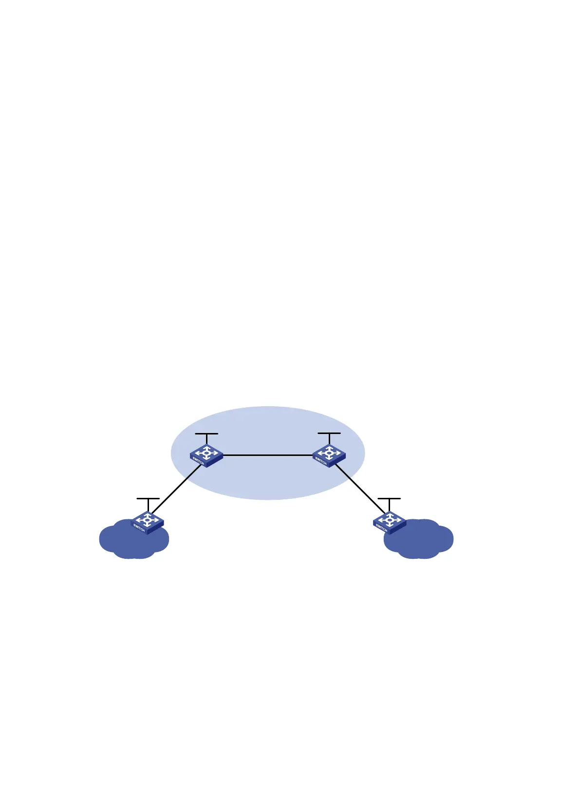
As shown in Figure 82, use 6PE to connect two isolated IPv6 networks over an IPv4/MPLS network.
• The ISP uses OSPF as the IGP.
• PE 1 and PE 2 are edge devices of the ISP, and establish an IPv4 IBGP connection between
them.
• CE 1 and CE 2 are edge devices of the IPv6 networks, and they connect the IPv6 networks to
the ISP.
• A CE and a PE exchange IPv6 packets through IPv6 static routing.
Figure 82 Network diagram
Configuration procedure
1. Configure IPv6 addresses and IPv4 addresses for interfaces. (Details not shown.)
2. Configure PE 1:
# Enable LDP globally, and configure the LSP generation policy.
<PE1> system-view
[PE1] mpls lsr-id 2.2.2.2
[PE1] mpls ldp
[PE1-ldp] lsp-trigger all
[PE1-ldp] quit
# Enable MPLS and LDP on VLAN-interface 30.
CE 1
PE 1
PE 2
IPv4/MPLS network
IBGP
CE 2
IPv6 network
Vlan-int30
1.1.1.1/16
Vlan-int30
1.1.1.2/16
Loop0
2.2.2.2/32
Loop0
3
.3.3.3/32
Vlan-int10
10::2/64
Vlan-int10
10::1/64
IPv6 network
Vlan-int20
20::2/64
Vlan-int20
20::1/64
Loop0
1::1/128
Loop0
4::4/128
AS 65100

 Loading...


