130
TableID: 0x2 OrigAs: 0
NibID: 0x26000002 LastAs: 0
AttrID: 0xffffffff Neighbor: 0.0.0.0
Flags: 0x1008c OrigNextHop: 10.1.1.100
Label: NULL RealNextHop: 10.1.1.100
BkLabel: NULL BkNextHop: N/A
Tunnel ID: Invalid Interface: Vlan-interface11
BkTunnel ID: Invalid BkInterface: N/A
FtnIndex: 0x0 TrafficIndex: N/A
Connector: N/A
The output shows that Switch A communicates with Switch B through VLAN-interface 11.
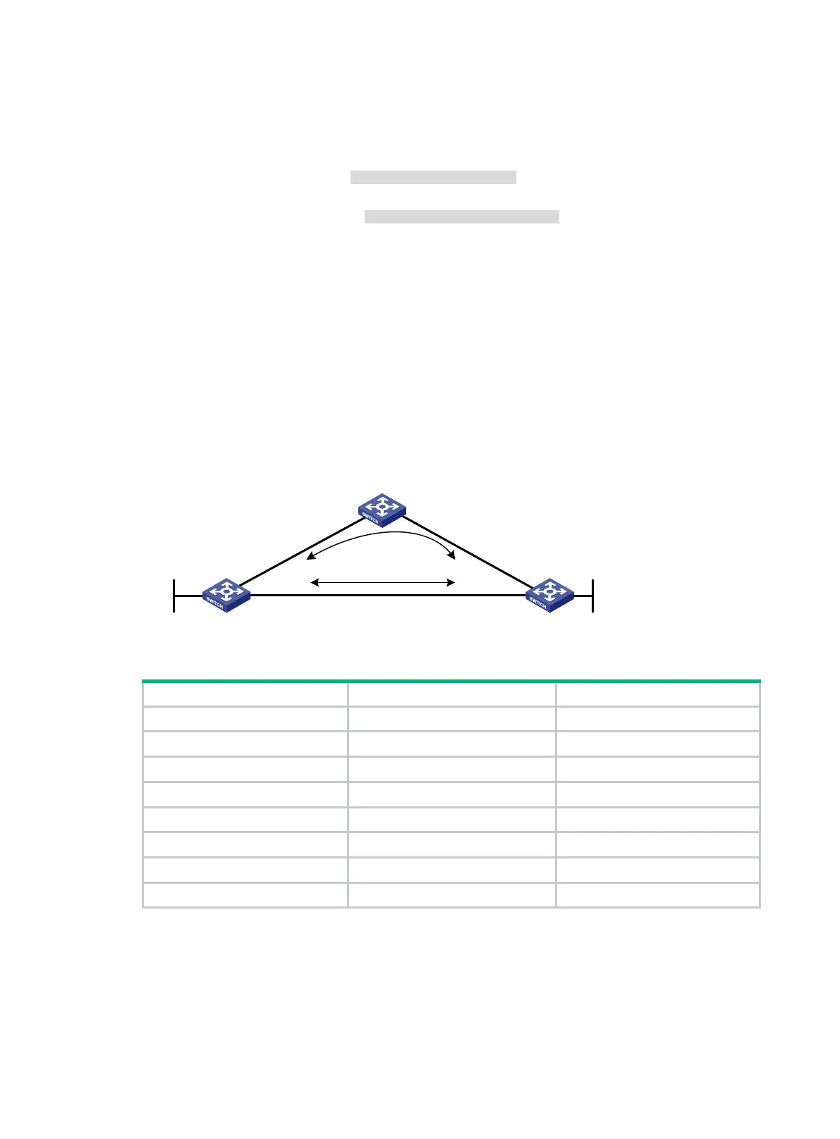
OSPF FRR configuration example
Network requirements
As shown in Figure 34, Switch A, Switch B, and Switch C reside in the same OSPF domain.
Configure OSPF FRR so that when the link between Switch A and Switch B fails, traffic is
immediately switched to Link B.
Figure 34 Network diagram
Table 10 Interface and IP address assignment
Switch A Vlan-int100 12.12.12.1/24
Switch A Vlan-int200 13.13.13.1/24
Switch A Loop0 1.1.1.1/32
Switch B Vlan-int101 24.24.24.4/24
Switch B Vlan-int200 13.13.13.2/24
Switch B Loop0 4.4.4.4/32
Switch C Vlan-int100 12.12.12.2/24
Switch C Vlan-int101 24.24.24.2/24
Configuration procedure
1. Configure IP addresses and subnet masks for interfaces on the switches. (Details not shown.)
2. Configure OSPF on the switches to ensure that Switch A, Switch B, and Switch C can
communicate with each other at the network layer. (Details not shown.)
3. Configure OSPF FRR to automatically calculate the backup next hop:
Switch A Switch B
Switch C
Loop0
Vlan-int100
Vlan-int200
Vlan-int200
Vlan-int100
Vlan-int101
Vlan-int101
Loop0
Link A
Link B

 Loading...


