478
Destination : 2001:1:: PrefixLen: 64
Flag : R/-/- Cost : 20
Next Hop : FE80::200:FF:FE0F:4 Interface: Vlan300
Destination : 2001:2:: PrefixLen: 64
Flag : R/-/- Cost : 20
Next Hop : FE80::200:FF:FE0F:4 Interface: Vlan300
Destination : 2001:3:: PrefixLen: 64
Flag : D/L/- Cost : 10
Next Hop : Direct Interface: Vlan300
Destination : 2001:4::1 PrefixLen: 128
Flag : D/L/- Cost : 0
Next Hop : Direct Interface: Loop1
Flags: D-Direct, R-Added to Rib, L-Advertised in LSPs, U-Up/Down Bit Set
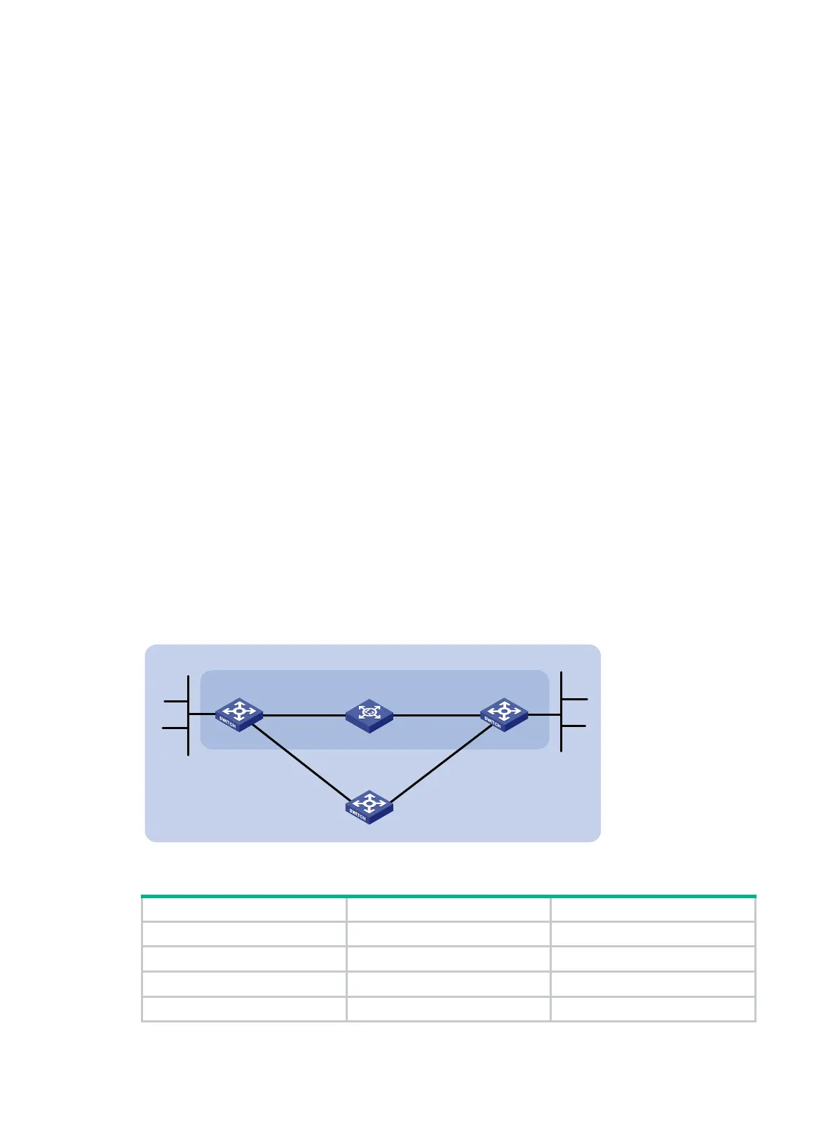
BFD for IPv6 IS-IS configuration example
Network requirements
As shown in Figure 113:
• Configure IPv6 IS-IS on Switch A and Switch B so that they can reach other.
• Enable BFD on VLAN-interface 10 of Switch A and Switch B.
After the link between Switch B and the Layer-2 switch fails, BFD can quickly detect the failure and
notify IPv6 IS-IS of the failure. Then Switch A and Switch B communicate through Switch C.
Figure 113 Network diagram
Table 27 Interface and IP address assignment
Switch A Vlan-int10 2001::1/64
Switch A Vlan-int11 2001:2::1/64
Switch B Vlan-int10 2001::2/64
Switch B Vlan-int13 2001:3::2/64
Switch A Switch B
Vlan-int10
Vlan-int10
BFD
L2 Switch
Area 0
Switch C
Vlan-int11
Vlan-int11
Vlan-int13
Vlan-int13
2001:4::/64
2001:1::/64

 Loading...


