409
Connector: N/A
# Display the route 10::1/128 on Switch B to view the backup next hop information.
[SwitchB] display ipv6 routing-table 10::1 128 verbose
Summary count : 1
Destination: 10::1/128
Protocol: RIPng
Process ID: 1
SubProtID: 0x0 Age: 00h22m34s
Cost: 1 Preference: 100
IpPre: N/A QosLocalID: N/A
Tag: 0 State: Inactive Adv
OrigTblID: 0x0 OrigVrf: default-vrf
TableID: 0xa OrigAs: 0
NibID: 0x22000001 LastAs: 0
AttrID: 0xffffffff Neighbor: FE80::34CC:E8FF:FE5B:C02
Flags: 0x41 OrigNextHop: FE80::34CC:E8FF:FE5B:C02
Label: NULL RealNextHop: FE80::34CC:E8FF:FE5B:C02
BkLabel: NULL BkNextHop: FE80::7685:45FF:FEAD:102
Tunnel ID: Invalid Interface: Vlan-interface200
BkTunnel ID: Invalid BkInterface: Vlan-interface101
FtnIndex: 0x0 TrafficIndex: N/A
Connector: N/A
RIPng IPsec profile configuration example
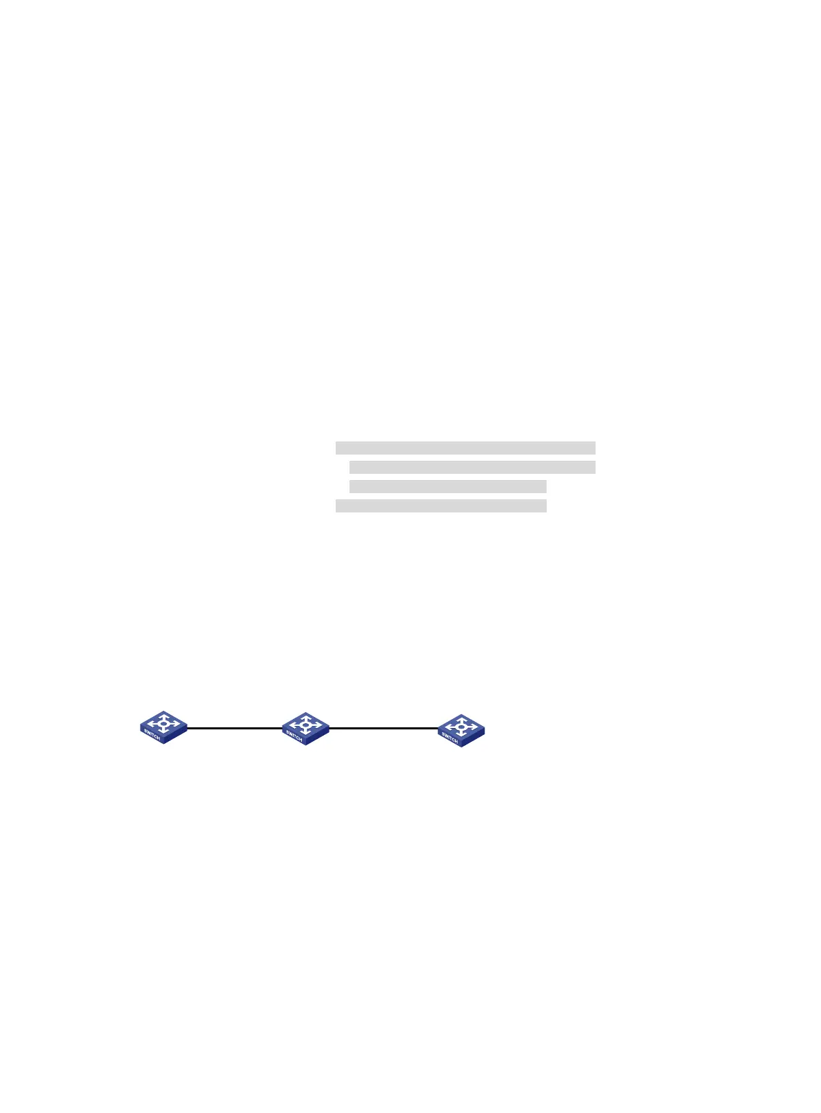
Network requirements
As shown in Figure 98, configure RIPng on the switches, and configure IPsec profiles on the
switches to authenticate and encrypt protocol packets.
Figure 98 Network diagram
Configuration procedure
1. Configure IPv6 addresses for interfaces. (Details not shown.)
2. Configure RIPng basic functions:
# Configure Switch A.
<SwitchA> system-view
[SwitchA] ripng 1
[SwitchA-ripng-1] quit
[SwitchA] interface vlan-interface 100
[SwitchA-Vlan-interface100] ripng 1 enable
[SwitchA-Vlan-interface100] quit
# Configure Switch B.
Vlan-int100
1::2/64
Vlan-int200
3::2/64
Vlan-int200
3::1/64
Vlan-int100
1::1/64
Switch A
Switch B
Switch C

 Loading...


